Operating Instructions
Modular Safety Control System MSC
72
(Translation of the original operating instructions) 2121331-04-04/19
9.1.10. Example for a project
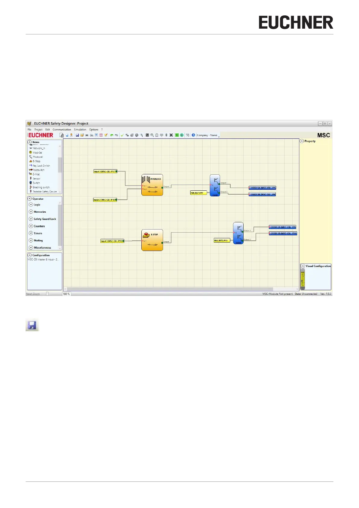
Figure 48 shows an example of a project in which the module MSC-CB is connected to only two safety components (interlock
and emergency stop).
The inputs (1, 2, 3) on the module MSC-CB for connecting the contacts on the safety components are highlighted in yellow
on the left. The MSC outputs (from 1 to 4) are activated as per the conditions that are specified in the interlock (INTERLOCK)
and emergency stop (E-STOP) (see page 81 Emergency stop (E-STOP) and page 83 Interlock (INTERLOCK)).
Click a block to select it and activate the PROPERTY window on the right where you can configure the activation and test
parameters for the block.
Figure 48: EUCHNER Safety Designer, project example
At the end of the project preparation phase (or during intermediate steps), you can save the actual configuration using the
button on the default toolbar.