Operating Instructions
Modular Safety Control System MSC
80
(Translation of the original operating instructions) 2121331-04-04/19
9.1.12. Checking the system
WARNING
After the project has been validated, uploaded to the module MSC-CB and all safety components have
been connected, the system must be checked for correct operation.
This check is made by forcing a status change for each safety component connected to MSC to check whether the status
of the outputs also actually changes.
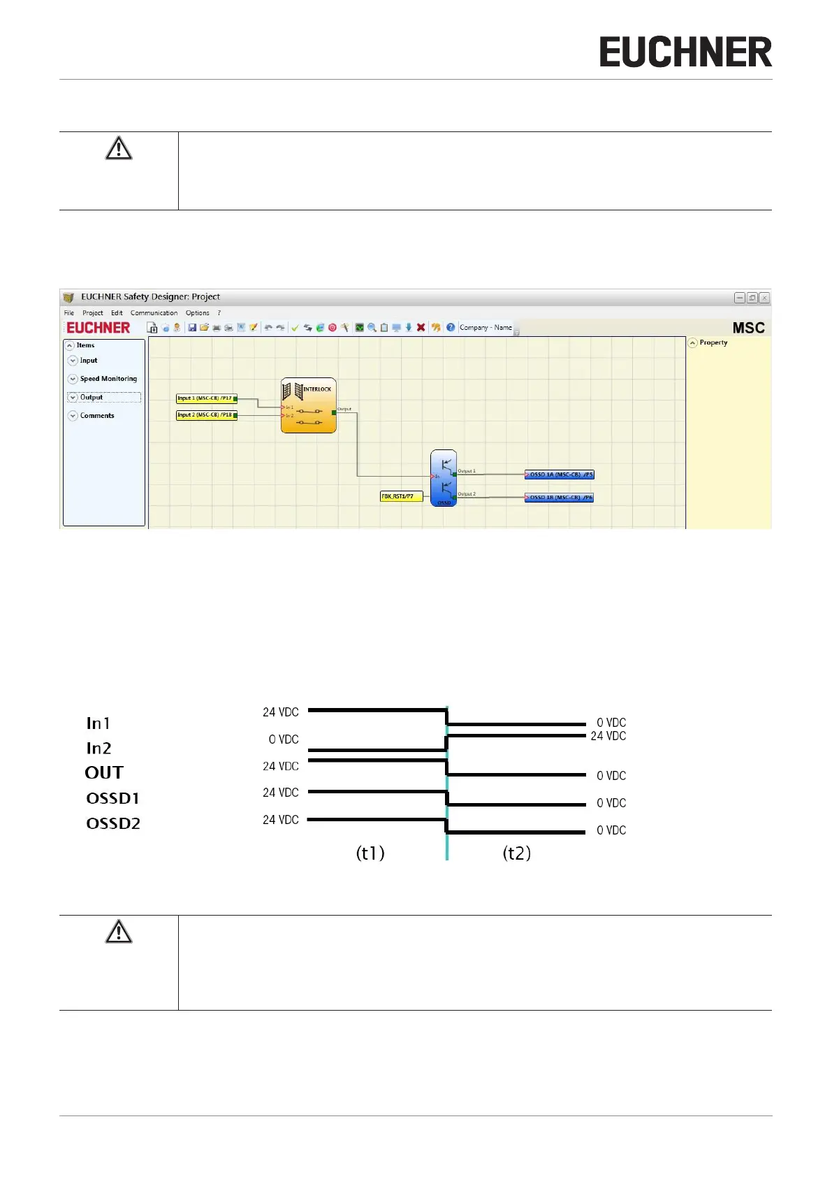
The following example is intended to explain the CHECK process.
Figure 58: Checking the system
(t1) In the normal operating status (interlock (INTERLOCK)) Input1 is closed, Input2 is open and the INTERLOCK output set
to the "HIGH" logic level. In this mode the safety outputs (OSSD1/2) are active and a supply voltage of 24 VDC is present
at the related terminals.
(t2) If the interlock (INTERLOCK) is opened physically, the state of the inputs changes and therefore also the outputs of
the INTERLOCK block: (OFF = 0 VDC ---> 24 VDC); The state of the safety outputs OSSD1/2 changes from 24 VDC
to 0 VDC. If this change is detected, the movable interlock (INTERLOCK) is connected correctly.
Figure 59: Change in the state of the system inputs/outputs
WARNING
Ì You will find more detailed information on the correct installation of external sensors/components
in the installation manual.
Ì This check must be undertaken for each safety component in the project.