www.cafection.com 800-561-6162
72
DS2212NSA Rev. 1 2023-04
SERVICE & INSTALLATION MANUAL - Symbol
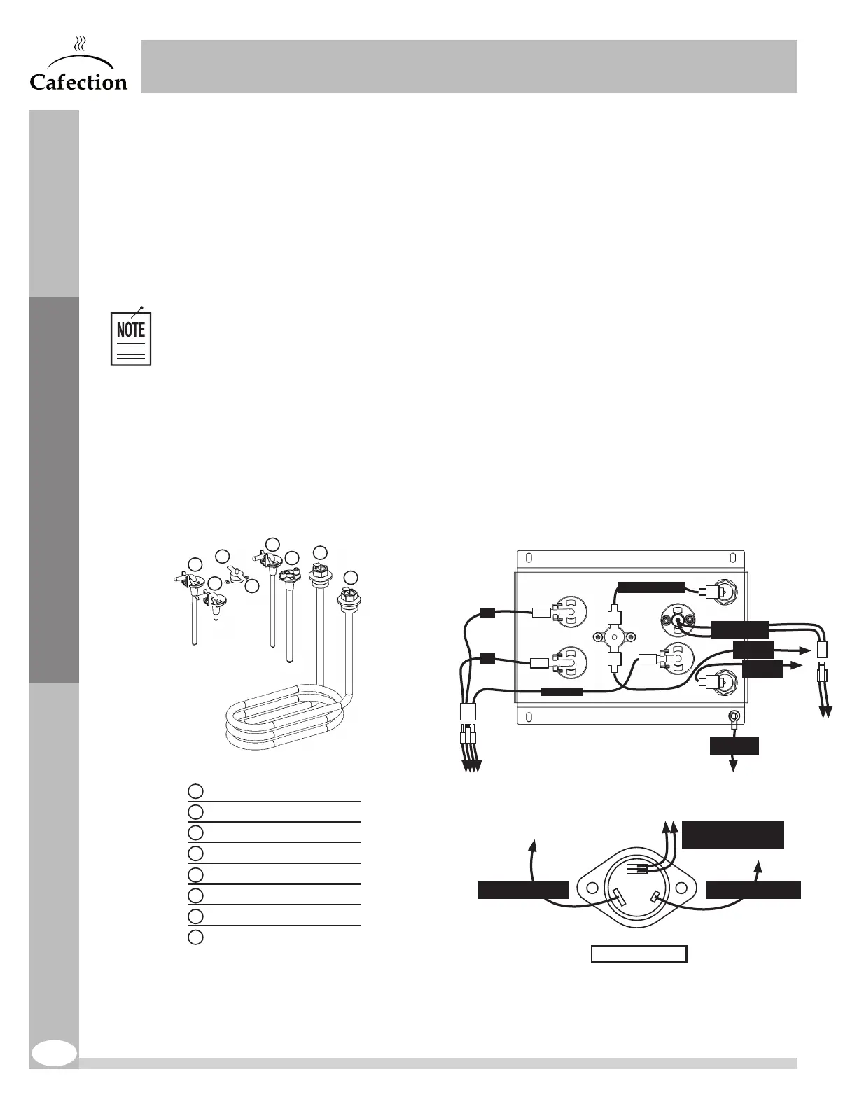
8.6 Hot Water Tank
Inspection: quarterly
Preventive maintenance: every 60,000 cycles
To avoid any issue related to mineral deposits, Evoca North America recommends having the water
tank assembly delimed to remove all scale in the unit. The heating element, probes and sensors
may also need to be replaced.
Use a scale remover product such as Scale Kleen by Everpure. See the
manufacturer’s instructions for more details.
1. Turn off the machine. then remove the back panel and the steam deflector.
2. Unplug the tank lid’s connectors.
3. Completely drain water from the tank (see section9.1).
4. Remove the tubes (valves and water tank).
5. Remove the tank.
6. To reinstall, follow steps in reverse order.
Preventive Maintenance
18LAB10A
Hot Water Tank Inner Components
Heating Element Connector 1
Heating Element Connector 2
Ground Reference Probe
Temperature Probe
Thermal Disk Connector 1
Thermal Disk Connector 2
Low Water Level Sensor (S1)
High Water Level Sensor (S2)
1
5
3
7
2
6
4
8
2
1
4
3
5
8
7
6
Power Triac
GATE - RED CONNECTOR
SINGLE WIRE
A1 - BLUE CONNECTOR
SEW WIRE
A2 - DOUBLE CONNECTOR
(TOP CONN. : RED
BOTTOM CONN. : BLACK)
Tank Lid - Top view
S1
S2
GND / REF
BLACK SEW WIRE
WHITE
SEW WIRE
BLACK
SEW WIRE
TANK-GND
GREEN WIRE
BLUE
BLUE
WHITE
WHITE
TEMPERATURE
PROBE WIRES
Valves Positions & Connectors
HOT WATER TANK - TOP VIEW
2
3
4
5
French Vanilla
Hot Water
Hot Chocolate
Milk Powder
Coffee
1 2
4
5
3
1
RED WIRE
BLACK WIRE
Grinder - Removal Instruction
1. Turne the brewer OFF.
2. Unplug connectors.
3. Remove plastic chute.
4. Unscrew the 4 Nuts.
Tool: Hex. socket 5/16”.
5. Remove grinder
assembly for servicing.
6. Screw grinder’s head
to the end; Unscrew to
align red lines.
7. Reinstall parts.
BLACK
WIRE
WHITE
WIRE
4X NUTS
TOOL: HEX. SOCKET 5/16”
GREEN
WIRE
RED LINES
ALIGNED
Valve 5 can be
removed from the
front of the machine.
*If a valve is replaced,
make sure the seal is
in place.
POWER TRIAC
23LAB08A rev 1
4,5 po (L) x 9,50 po (H)
Rayons des coins: 0,125 po
INSTALLATION &
SERVICE MANUAL
Available by scanning
this QR code
HOT WATER TANK - INNER COMPONENTS
Cafection - 18LAB10F - rev 1
Réservoir d’eau chaude — Pièces internes
Élément chauffant : Connecteur 1
Élément chauffant : Connecteur 2
Sonde de mise à la terre
Sonde de température
Disque thermique : Connecteur 1
Disque thermique : Connecteur 2
Sonde de niveau d’eau bas (S1)
Sonde de niveau d’eau haut (S2)
1
5
3
7
2
6
4
8
2
1
4
3
5
8
7
6
Position des valves et de leurs connecteurs
RÉSERVOIR D’EAU CHAUDE -
VUE DE DESSUS
2
3
4
5
Vanille française
Eau chaude
Chocolat chaud
Lait en poudre
Café
1 2
4
5
3
1
CÂBLE ROUGE
CÂBLE NOIR
Réservoir d’eau chaude - Vue de dessus
S1
S2
GND / REF
CÂBLE SEW NOIR
CÂBLE SEW
BLANC
CÂBLE
SEW NOIR
TANK-GND
CÂBLE VERT
BLEU
BLEU
BLANC
BLANC
CÂBLE SONDE DE
TEMPÉRATURE
La valve 5 peut être
retirée par l’avant de
la machine.
*Si une valve est
remplacée, s’assurer
que le joint torique
est bien en place.
18LAB10A
Hot Water Tank Inner Components
Heating Element Connector 1
Heating Element Connector 2
Ground Reference Probe
Temperature Probe
Thermal Disk Connector 1
Thermal Disk Connector 2
Low Water Level Sensor (S1)
High Water Level Sensor (S2)
1
5
3
7
2
6
4
8
2
1
4
3
5
8
7
6
Tank Lid - Top view
S1
S2
GND / REF
BLACK SEW WIRE
WHITE
SEW WIRE
BLACK
SEW WIRE
TANK-GND
GREEN WIRE
BLUE
BLUE
WHITE
WHITE
TEMPERATURE
PROBE WIRES
Valves Positions & Connectors
HOT WATER TANK - TOP VIEW
2
3
4
5
French Vanilla
Hot Water
Hot Chocolate
Milk Powder
Coffee
1 2
4
5
3
1
Valve 5 can be
removed from the
front of the machine.
*If a valve is replaced,
make sure the seal is
in place.
HOT WATER TANK - TOP VIEW
Whipper
Coffee
Hot Water
RED CABLE
BLACK CABLE
23LAB08A - REV. 1
18LAB10A
Hot Water Tank Inner Components
Heating Element Connector 1
Heating Element Connector 2
Ground Reference Probe
Temperature Probe
Thermal Disk Connector 1
Thermal Disk Connector 2
Low Water Level Sensor (S1)
High Water Level Sensor (S2)
1
5
3
7
2
6
4
8
2
1
4
3
5
8
7
6
Power Triac
GATE - RED CONNECTOR
SINGLE WIRE
A1 - BLUE CONNECTOR
SEW WIRE
A2 - DOUBLE CONNECTOR
(TOP CONN. : RED
BOTTOM CONN. : BLACK)
Tank Lid - Top view
Valves Positions & Connectors
HOT WATER TANK - TOP VIEW
2
3
4
5
French Vanilla
Hot Water
Hot Chocolate
Milk Powder
Coffee
1 2
4
5
3
1
RED WIRE
BLACK WIRE
Grinder - Removal Instruction
1. Turne the brewer OFF.
2. Unplug connectors.
3. Remove plastic chute.
4. Unscrew the 4 Nuts.
Tool: Hex. socket 5/16”.
5. Remove grinder
assembly for servicing.
6. Screw grinder’s head
to the end; Unscrew to
align red lines.
7. Reinstall parts.
BLACK
WIRE
GREEN
WIRE
Valve 5 can be
removed from the
front of the machine.
*If a valve is replaced,
make sure the seal is
in place.
TEMPERATURE
PROBE WIRES
S1
S2
GND / REF
BLACK SEW WIRE
WHITE
SEW WIRE
BLACK
SEW WIRE
TANK-GND
GREEN WIRE
BLUE
BLUE
WHITE
WHITE
23LAB08A rev 1
4,5 po (L) x 9,50 po (H)
Rayons des coins: 0,125 po
INSTALLATION &
SERVICE MANUAL
Available by scanning
this QR code
HOT WATER TANK - INNER COMPONENTS
Cafection - 18LAB10F - rev 1
Réservoir d’eau chaude — Pièces internes
Élément chauffant : Connecteur 1
Élément chauffant : Connecteur 2
Sonde de mise à la terre
Sonde de température
Disque thermique : Connecteur 1
Disque thermique : Connecteur 2
Sonde de niveau d’eau bas (S1)
Sonde de niveau d’eau haut (S2)
1
5
3
7
2
6
4
8
Position des valves et de leurs connecteurs
RÉSERVOIR D’EAU CHAUDE -
VUE DE DESSUS
2
3
4
5
Vanille française
Eau chaude
Chocolat chaud
Lait en poudre
Café
1 2
4
5
3
1
CÂBLE ROUGE
CÂBLE NOIR
Réservoir d’eau chaude - Vue de dessus
S1
S2
GND / REF
CÂBLE SEW NOIR
CÂBLE SEW
BLANC
CÂBLE
SEW NOIR
TANK-GND
CÂBLE VERT
BLEU
BLEU
BLANC
BLANC
CÂBLE SONDE DE
TEMPÉRATURE
La valve 5 peut être
retirée par l’avant de
la machine.
*Si une valve est
remplacée, s’assurer
que le joint torique
est bien en place.
18LAB10A
Hot Water Tank Inner Components
Heating Element Connector 1
Heating Element Connector 2
Ground Reference Probe
Temperature Probe
Thermal Disk Connector 1
Thermal Disk Connector 2
Low Water Level Sensor (S1)
High Water Level Sensor (S2)
1
5
3
7
2
6
4
8
2
1
4
3
5
8
7
6
Tank Lid - Top view
S1
S2
GND / REF
BLACK SEW WIRE
WHITE
SEW WIRE
BLACK
SEW WIRE
TANK-GND
GREEN WIRE
BLUE
BLUE
WHITE
WHITE
TEMPERATURE
PROBE WIRES
Valves Positions & Connectors
HOT WATER TANK - TOP VIEW
2
3
4
5
French Vanilla
Hot Water
Hot Chocolate
Milk Powder
Coffee
1 2
4
5
3
1
Valve 5 can be
removed from the
front of the machine.
*If a valve is replaced,
make sure the seal is
in place.
HOT WATER TANK - TOP VIEW
Whipper
Coffee
Hot Water
RED CABLE
BLACK CABLE
23LAB08A - REV. 1
18LAB10A
Hot Water Tank Inner Components
Heating Element Connector 1
Heating Element Connector 2
Ground Reference Probe
Temperature Probe
Thermal Disk Connector 1
Thermal Disk Connector 2
Low Water Level Sensor (S1)
High Water Level Sensor (S2)
1
5
3
7
2
6
4
8
2
1
4
3
5
8
7
6
Power Triac
GATE - RED CONNECTOR
SINGLE WIRE
A1 - BLUE CONNECTOR
SEW WIRE
A2 - DOUBLE CONNECTOR
(TOP CONN. : RED
BOTTOM CONN. : BLACK)
Tank Lid - Top view
Valves Positions & Connectors
HOT WATER TANK - TOP VIEW
2
3
4
5
French Vanilla
Hot Water
Hot Chocolate
Milk Powder
Coffee
1 2
4
5
3
1
RED WIRE
BLACK WIRE
Grinder - Removal Instruction
1. Turne the brewer OFF.
2. Unplug connectors.
3. Remove plastic chute.
4. Unscrew the 4 Nuts.
Tool: Hex. socket 5/16”.
5. Remove grinder
assembly for servicing.
6. Screw grinder’s head
to the end; Unscrew to
align red lines.
7. Reinstall parts.
BLACK
WIRE
GREEN
WIRE
Valve 5 can be
removed from the
front of the machine.
*If a valve is replaced,
make sure the seal is
in place.
TEMPERATURE
PROBE WIRES
S1
S2
GND / REF
BLACK SEW WIRE
WHITE
SEW WIRE
BLACK
SEW WIRE
TANK-GND
GREEN WIRE
BLUE
BLUE
WHITE
WHITE