74 02-2023 6095 00
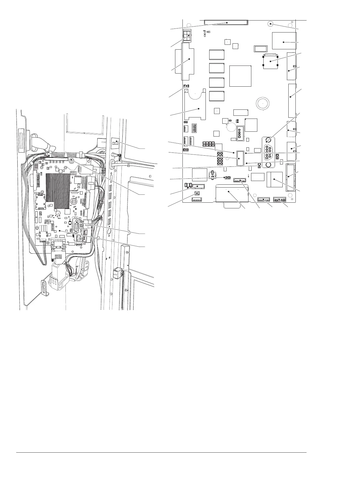
CPU BOARD
The CPU board manages the communica-
tion with the touch screen, with payment
systems and connectivity functions.
The Wi-Fi aerial is connected at the
back of the CPU board.
The aerial and the relative connec-
tor are very delicate, pay attention not
to damage them when you remove the
CPU board (e.g. for replacement).
1
2
4
3
Fig. 47
1. C.P.U. board
2. RS232 serial port
3. Wi-Fi aerial connector*
4. Mechanical counter (if any)
*. at the back of the board
1
2
3
4
5
6
7
8
9
10
11
13
12
14
15
16
17
18
19
22
21
20
23
24
2627
25
Fig. 48
1. (J2) connectivity switch
2. (CN30) not used
3. (JP2) can bus jumper 1 closed
4. (JP5) can bus jumper 2 open
5. usb otg port
6. Yellow led reset
7. SIM card slot*
8. (JP4) sim card jumper
9. (J16) dvi connector
10. (CN31) touch screen lighting
11. (CN55) Bus i2c
12. (CN33) Wi-Fi aerial connector**
13. Ethernet connector (1 Gbit/s)
14. micro sd* slot
15. (J42) service buttons and counter*
16. (J43) digital inputs / outputs
17. rs232 serial connector
18. (J41) not used
19. (J35) Payment systems
20. Red led power supply
21. Green led run
22. (J36) Validator
23. Ethernet connector (100 Mbit/s)
24. (CN9) touch screen connector
25. (J47) not used
26. (CN34) not used
27. (CN29) can bus touch screen
*. If any
**. At the back of the board