Examples of Valid Stacking Congurations
The examples in the following sections show various physical stacking arrangements:
all switches in a single rack, switches in two adjacent racks, and switches at the tops of
several racks in a row.
Example: Basic Stack with Four Switches
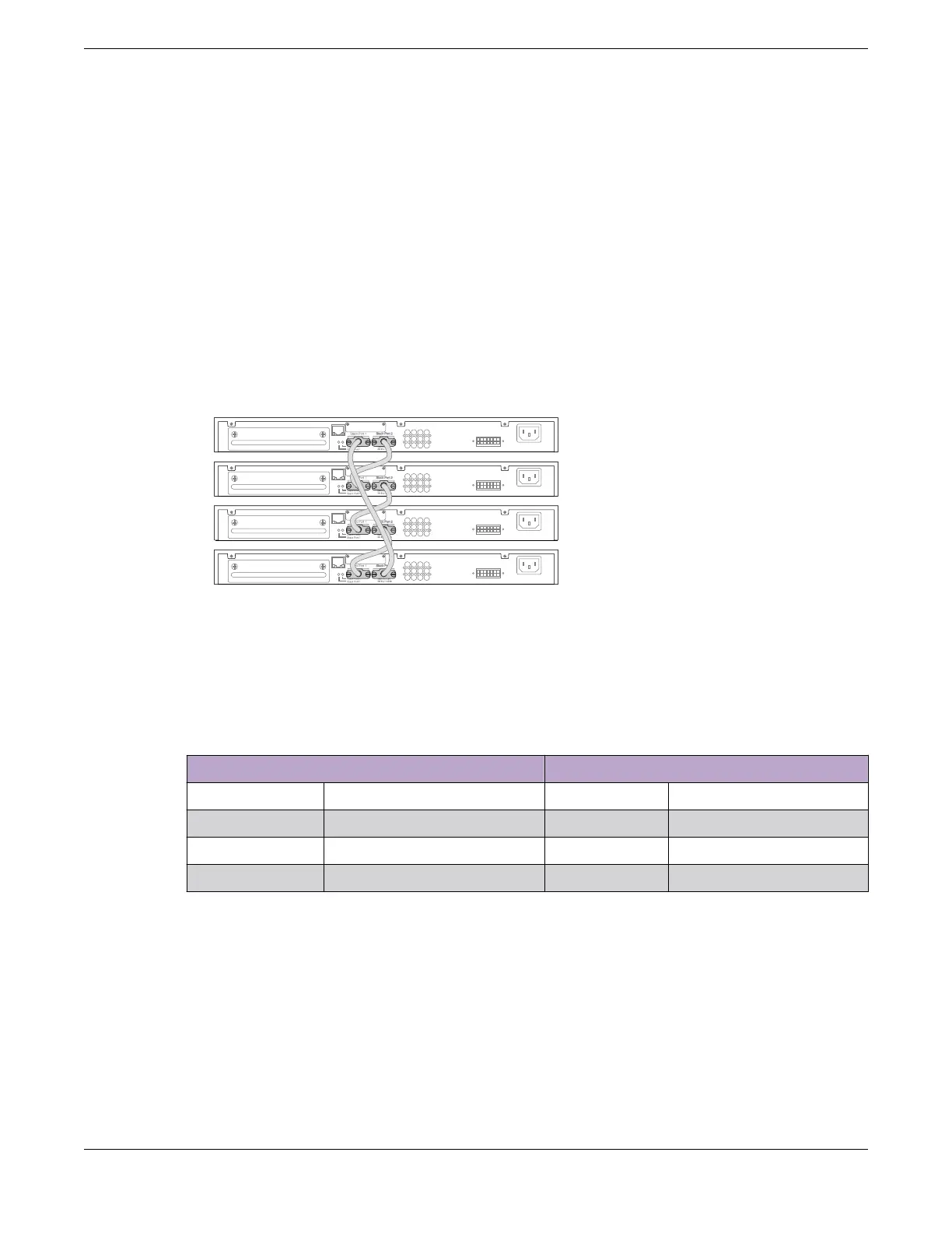
This example shows a stack of four switches in a single rack.
The slot numbers presume a console connection to the switch at the top of the physical
stack.
Figure 29 shows cable connections for a 4-node stack using SummitStack 40G cables
to connect switches with integrated SummitStack ports.
Figure 29: SummitStack Cable Connections Using Four Switches with Integrated
SummitStack Ports
Table 10 lists the recommended order for connecting the stacking ports in this
example.
Table 10: Basic Stack with Four Switches: Connections
Connect this slot and port . . . . . . To this slot and port
Slot 1 Stack Port 2 Slot 2 Stack Port 1
Slot 2 Stack Port 2 Slot 3 Stack Port 1
Slot 3 Stack Port 2 Slot 4 Stack Port 1
Slot 4 Stack Port 2 Slot 1 Stack Port 1
Example: Basic Stack with Eight Switches
Figure 30 shows cable connections for an 8-node stack using SummitStack 40G cables
to connect switches with integrated SummitStack ports.
Connect the Switches to Form the Stack Ring Build Stacks
56 ExtremeSwitching 5320 Series Hardware Installation Guide

 Loading...

