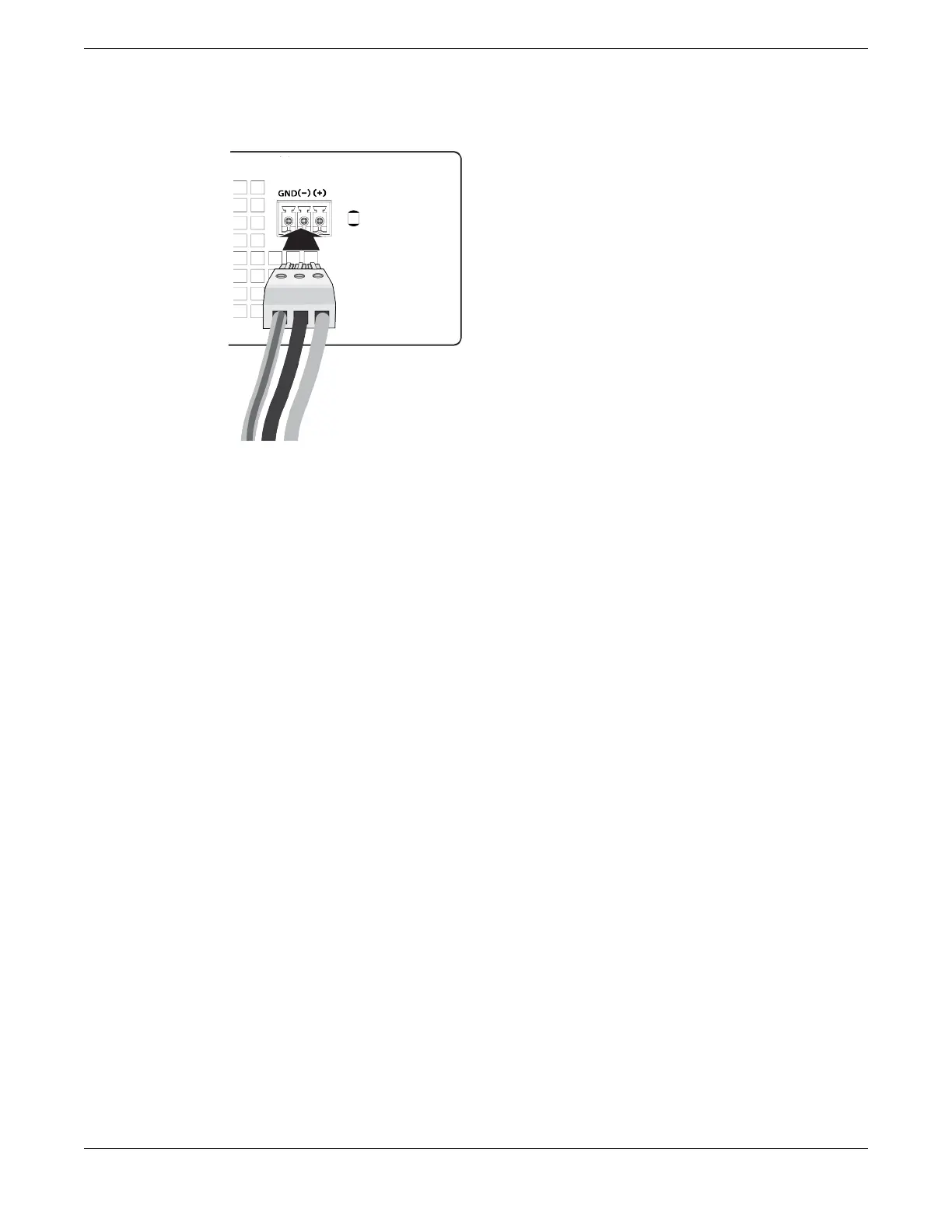
6. Insert the connector into the slot on the power supply.
Figure 61: Inserting the DC terminal connector into the slot on the power supply
7. Connect the power cables to the DC source voltage, using hardware appropriate to
the installation site and following local and national electrical codes.
8. Energize the circuit. When power is connected, verify that the PWR LED is green.
When the PWR LED has turned green, follow the instructions in Activate and Verify the
Switch on page 81.
If the PWR LED does not turn green, refer to 5320 Series Switch LEDs on page 89 for
troubleshooting information.
Connect DC Power Install Your Switch
80 ExtremeSwitching 5320 Series Hardware Installation Guide

 Loading...

