DTP CrossPoint 84 Series Matrix Switchers • Matrix Software 124
2. Open the ducking dialog box for the input and select the desired duck targets. In this
example mics 3 and 4 are the ducking targets of mic 2.
Any signal on input #2 that exceeds the ducking threshold now ducks mics 3 and 4.
The ducking targets can be changed at any time by double-clicking the mic 2 ducking
processor block.
Since mic 2 is a target of mic 1, if a signal on mic 1 exceeds the ducking threshold,
mics 2 through 4 are still ducked regardless of whether the signal on mic 2 exceeds its
ducking threshold.
NOTE: No input will be ducked more than the amount set in the applicable
by (dB): field.
Expansion Port Operation Within the DSP
The expansion port (see DMP Expansion Port and LED on page14) allows a DTP
CrossPoint matrix switcher and an Extron DMP 128 ProDSP Digital Matrix Processor to be
connected together for bidirectional communications with 16 channels of output audio and
8 channels of input audio. Audio that is processed in one unit can be directly input to the
other unit to harness its processing capabilities.
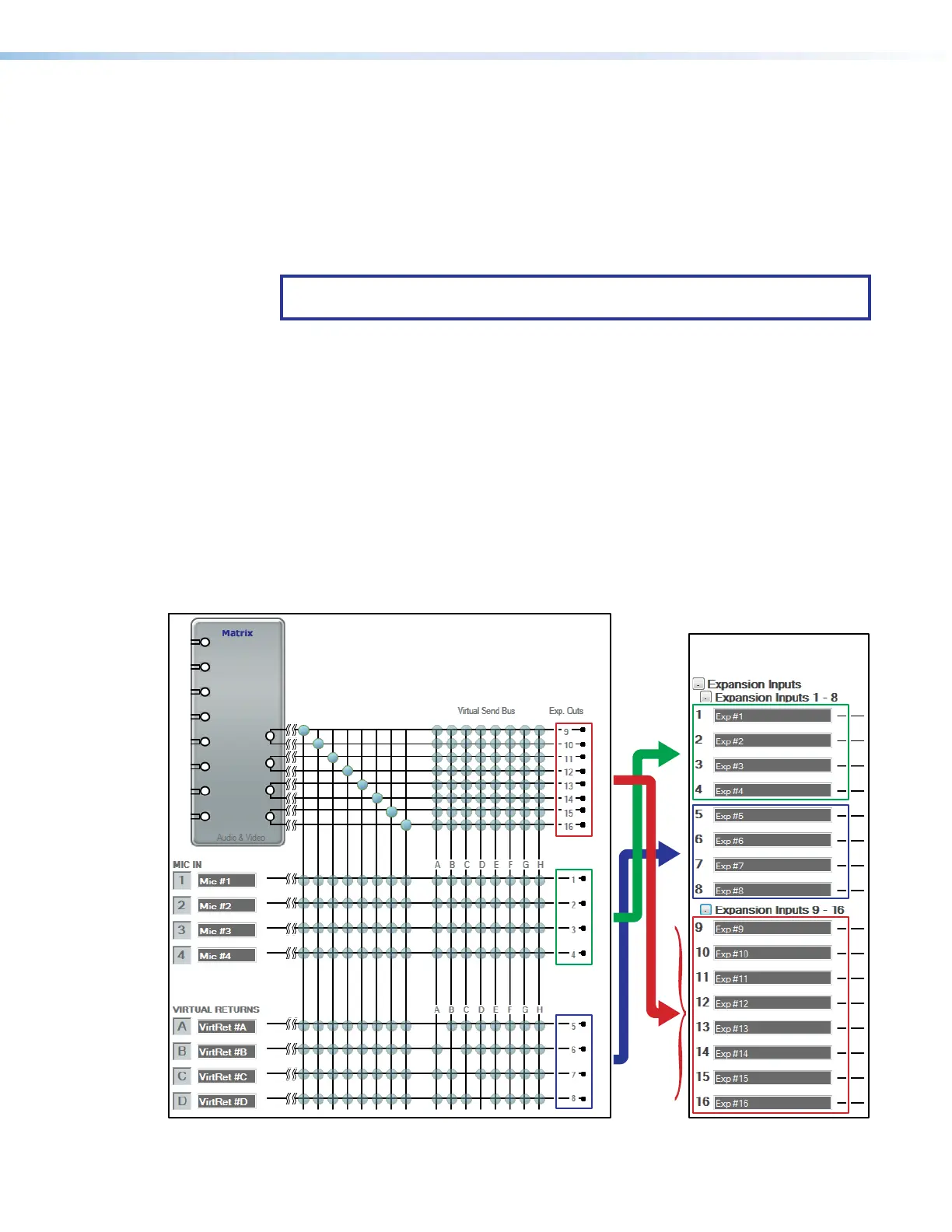
Expansion output channels
The DTP CrossPoint has 16 expansion output channels (see figure74), comprised of:
• Mic inputs 1 through 4 (channels 1 through 4)
• Virtual returns A through D (channels 5 through 8)
• Line outputs 1 through 4, left and right (channels 9 through 16)
DTP CrossPoint 84
DMP 128 ProDSP
Digital Matrix Processor
}
}
}
}
Figure 74. Expansion Output Channels
70