DTP CrossPoint 84 Series Matrix Switchers • Installation 11
Rear Panel Cabling and Features
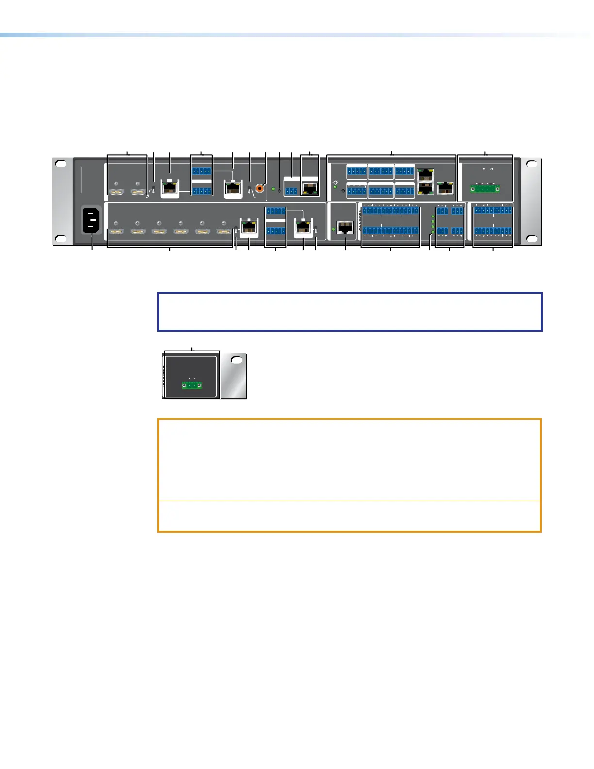
The non-IPCP, SA, and MA models have similar features, with differences in the control
connections and Amplified Output block only. Figure 2 shows the rear panel of a composite
DTP CrossPoint 84 model, featuring elements of different models. Figure 3 shows only the
Amplified Output block portion of the DTP CrossPoint 84 IPCP MA rear panel.
50-60 Hz
100-240V ~
2.0 A MAX
1
L
R
SIG LINK
OUT
SIG LINK
OUT
1
3
4
4
XTP
RS-232 IR
Tx Rx
RTSCTS
GTxRxG Tx Rx G
RS-232 IR
Tx Rx Tx RxG
Tx Rx Tx Rx
XTP
RESET
S/PDIF
OUT
DTP
XTP
DTP
XTP
DTP
EXP
+48V
MIC/LINE
1
1
3
2
4
2
3
4
LINK
LAN 2
LAN 1
LAN 3
HDBT
G
DTP
HDBT
2
1234
5
7
8
6
DTP CROSSPOINT 84
4
CLASS 2 WIRING
8/
R
RS-232 IR
Tx Rx Tx RxG
OVER TP
OVER TP
SIG LINK
IN
SIG LINK
IN
AUDIO INPUTS
AUDIO OUTPUTS
AMP OUTPUT
CONTROL
1234G
DIGITAL I/OCOM 3COM 2COM 1
S
DMP EXPANSION
SGG
1
1
2
2
C34C
INPUTS
-S G+S+V
PWR OUT = 6W
OUTPUTS
RS-232 IR
Tx Rx Tx RxG
1
LR
1
LR
3
LR
3
LR
5
LR
2
LR
4
LR
2
LR
4
LR
6
LR
IR/SERIAL eBUSRELAYS
Tx Rx G
REMOTE LAN
BB BB NN
FFEE EE MM SSTTFF
CC CCAA OO GG HHIIJJUU
DD
PP RRQQ KK
Figure 2. DTP CrossPoint 84 Matrix Switcher Rear Panel
(showing non-IPCP LAN port, IPCP, and SA [Stereo Audio) Components)
NOTE: Figure 2 is a composite that shows features of all models. Actual models can
have either item
Q
or item
R
, but not both. Models with
R
also have either item
K
or
L
(see figure3).
AMP OUTPUT
CLASS 2 WIRING
1
70V
Figure 3. DTP CrossPoint 84 IPCP MA (Mono Audio) Amplified Output Block
ATTENTION:
• Use electrostatic discharge (ESD) precautions (be electrically grounded) when
making connections. Electrostatic discharge can damage equipment, even if you
cannot feel, see, or hear it.
• Prenez des précautions contre les décharges électrostatiques (soyez
électriquement relié à la terre) lorsque vous effectuez des connexions.
•
Remove system power befor
e making all connections.
• Débranchez l’alimentation du système avant de faire n’importe quelle connexion.
A
HDMI Inputs 1 through 6
B
Input TP function switches
C
TP Inputs 7 and 8
D
HDMI OUTPUTS 1 and 2
E
Output TP function switches
F
TP Outputs 3 and 4
G
Audio Inputs 1 through 6
H
Mic/Line Inputs 1 through 4
I
+48 V (phantom power) LEDs
J
Audio Outputs 1 through 4
K
Amp OUTPUTS 1 (SA Model)
L
Amp Output 1 Amp OUTPUTS
1 (MA Model)
M
S/PDIF OUTPUTS 44
N
DMP Expansion Port and LED
O
Over TP (Inputs 7 and 8) ports
P
Over TP (Outputs 3 and 4) ports
Q
LAN port
R
IPCP Pro 350 processor
S
Remote Port
T
Switcher Reset button and LED
U
Power connector
2
3