DTP CrossPoint 84 Series Matrix Switchers • Installation 12
Video and TP Input and Output Connections and Switches
SIG LINK
OUT
1
3
4
4
XTP
RS-232 IR
RS-232 IR
Tx Rx Tx RxG
Tx Rx Tx Rx
XTP
S/PDIF
OUT
DTP
XTP
DTP
XTP
DTP
HDBT
G
DTP
HDBT
2
1234
5
7
8
6
RS-232 IR
Tx Rx Tx RxG
OVER TP
OVER TP
SIG LINK
IN
RS-232 IR
Tx Rx Tx RxG
SIG LINK
OUT
SIG LINK
IN
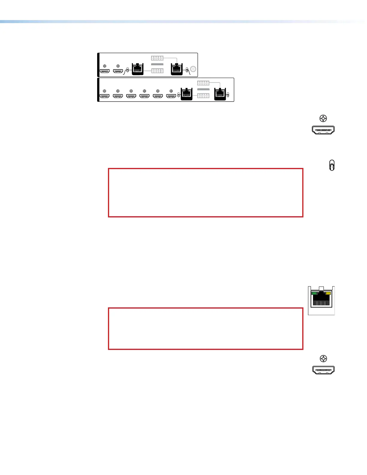
Figure 4. Video and TP Input and Output Connections and Switches
A
HDMI Inputs 1 through 6 (see figure2 on page11)— Plug HDMI digital
video sources into the matrix switcher via these HDMI connectors. These
connectors can also accept DVI video with appropriate adapters. See HDMI
connectors on page 16 for pin assignments and to use the LockIt HDMI
Cable Lacing Bracket to secure the connector to the transmitter.
B
Input TP function switches, inputs 7 and 8 — These switches tailor the
switcher to accept input 7 and 8 signals as follows:
ATTENTION:
• Position this switch BEFORE connecting the appropriate device to
the TP connector. Failure to comply can damage the endpoint.
• Positionnez le sélecteur AVANT de connecter l’appareil approprié
au connecteur TP. Ne pas respecter cette procédure pourrait
endommager le point de connexion.
XTP position — If the transmitting device is an XTP CrossPoint matrix
switcher, set this switch to the XTP position. The TP input comes from an
XTP CrossPoint matrix switcher and consists of HDMI with embedded audio
plus RS-232 and IR.
DTP position — If the connected transmitting device is in the Extron DTP
series, set this switch to the DTP position. The TP input comes from a DTP
transmitting device and consists of HDMI with embedded audio, analog
audio, RS-232 and IR, and remote power.
C
TP Inputs 7 and 8 — Connect STP cables between compatible Extron
IN
DTP transmitting devices or XTP matrix switchers and these RJ-45
connectors (see TP connectors on page 17 to wire the connector).
ATTENTION:
•
Do not connect this port to a computer data or
telecommunications network.
•
Ne connectez pas ces port à des données informatiques ou à un
r
éseau de télécommunications.
D
HDMI output 1 and 2 — Connect HDMI cables between these ports and
HDMI video displays. See HDMI connectors on page 16 for pin assignments
and to use the LockIt HDMI Cable Lacing Bracket to secure the connector
to the transmitter.
4
HDMI Inputs 1 through 6
Input TP function switches
TP Inputs 7 and 8
HDMI OUTPUTS 1 and 2