RESTRICTED USE ONLY Fargo Electronics, Inc.
DTC500 Series Card Printer/Encoders User Guide (Rev. 5.0)
144
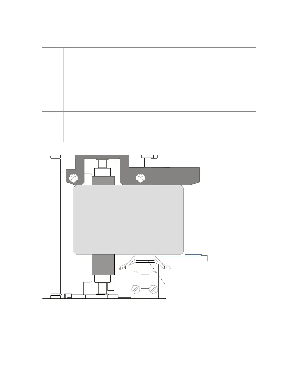
Adjusting the Internal Card Guide (continued)
Step Procedure
2 Slightly loosen the two screws which fasten the Internal Card Guide to the
Printer's main chassis.
3 Move the Internal Card Guide so there is a slight space of about .010"/.25mm
between the card edge and the Internal Card Guide as indicated below.
When adjusting the Internal Card Guide, be sure it always remains parallel to
the Card Guide Rail and card edge.
4 Always make very slight adjustments to the Internal Card Guide and run a test
print after each adjustment until the optimum position is found. (Note: Be sure
the Internal Card Guide always remains parallel to the card path and that the
screws loosened in Step 1 are retightened after each adjustment.)
space
CR100
CR90
CR80