Chapter 4 Installation and Wiring
PAGE 4-14
[Output Signals]
When an output signal is “ON,” the voltage at the corresponding output terminal is at the same level as
the output common voltage (0V if wired for NPN, 24V if wired for PNP).
MANREV / RELAY CONTACT-1 SIGNAL PIN No.: TB2-7 OUT-8
RELAY CONTACT –COM SIGNAL PIN No.: TB2-10
Turns ON by manually starting the reverse operation (By TB1 REVERSE signal or by tool REVERSE
switch on and trigger activated) .
Turns OFF when the next fastening starts, or turns “OFF” at RESET, BYPASS/PROGRAM.
For details, refer to Section 4-5-5 [MANREV signal timing chart]
RELAY CONTACT-2 SIGNAL PIN No.: TB2-8 OUT-9
RELAY CONTACT –COM SIGNAL PIN No.: TB2-10
Duplicates the controller BUZZER - Performs output of the REJECT and Batch OK signals to
external devices according to the timing below.
Turns ON for 0.4 seconds by the BATCH OK signal rising edge.
Turns ON for 0.1 seconds by the QL OK signal rising edge.
Note: if using for a REJECT signal, signal must be ON for more than 0.4sec to signify REJECT
RELAY CONTACT-3 SIGNAL PIN No.: TB2-9 OUT-10
RELAY CONTACT –COM SIGNAL PIN No.: TB2-10
Relay is ON when the fastening has been performed for the number of times specified by the Batch
cycle count.
QL OK RELAY CONTACT-4 SIGNAL PIN No.: TB2-11 OUT-11
QL OK RELAY CONTACT-4 SIGNAL PIN No.: TB2-12 OUT-11
OK output for the QL signal
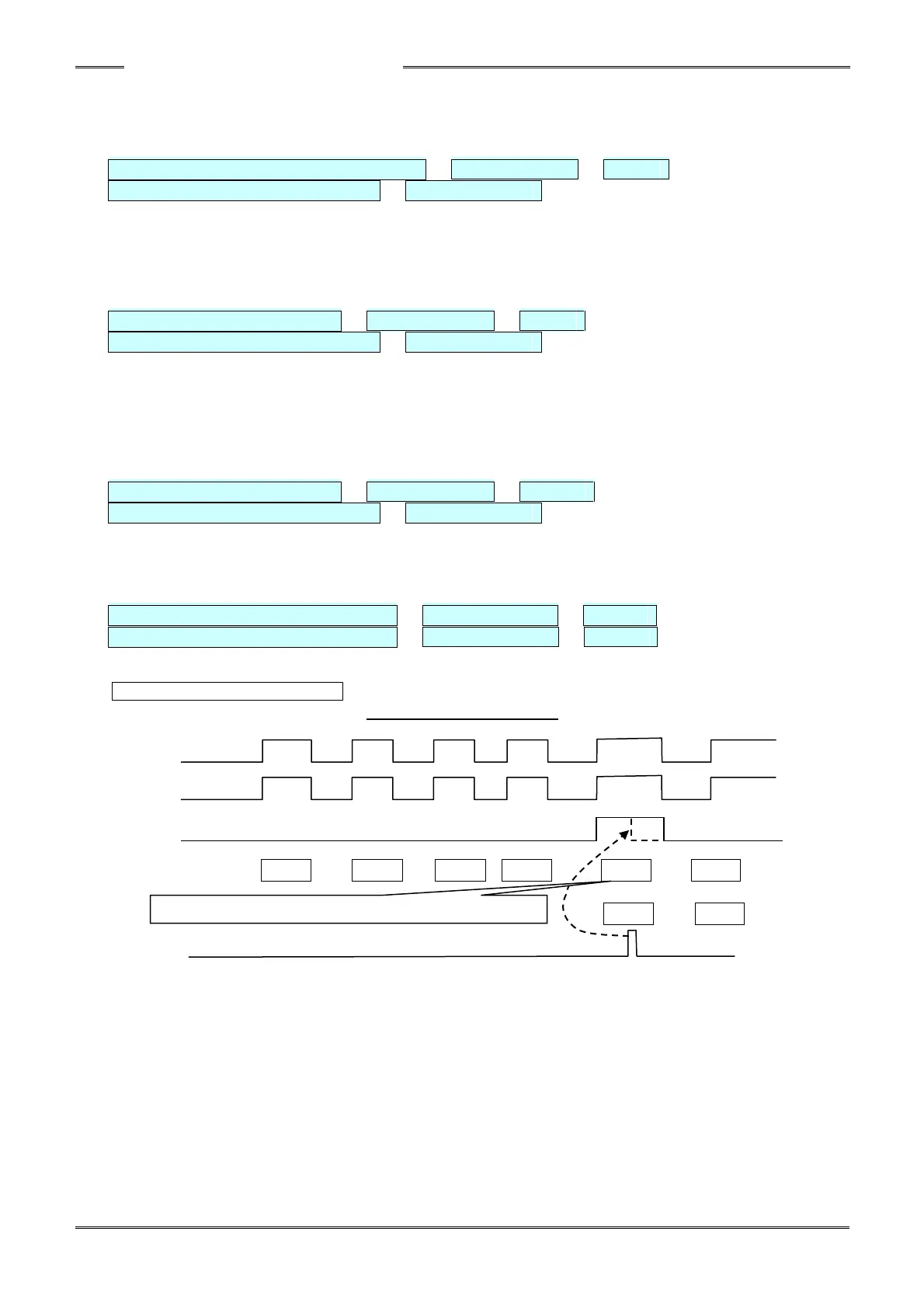
[QL OK] [BATCH OK] Timing Chart
D-No.540: Cycle count = 5
ACCEPT
QL OK
BATCH OK
D-No/COUNT
BATCH OK RESET