6 Positioning mode
154 Festo – GDCP-CMMS/D-FW-EN – 1404NH – English
6.8 Homing mode/homing
6.8.1 Function: Homing mode
In the homing mode, the homing point of the dimension reference system is ascer tained via homing.
The homing point is the absolute point of reference for the axis zero point and the project zero point of
the dimension reference system. Homing can be execute d via the active fieldbus (CANopen/DriveBus/
PROFIBUS DP/DeviceNet/RS485), the digital inputs (mode 0 page 49) or the Festo Configuration
Tool ( FCT). Through direct application or record selection (positioning record 0) the c ontroller-internal
positioning controller receives the homing parameters. The c ontroller-internal positioning controller
calculates the homing curve from these parameters and transfers the position setpoint values cyclically
to the position control. The homing parameters can be parameterised via fieldbus or the Festo Config-
uration Tool (FCT).
For homing, the following settings must be parameterised in the Festo Configuration Tool (FCT):
–Homing page 161
– Measuring system page 75
Note
When using drives with a single-turn absolute encoder (CMMS/D-AS) or incremental
encoder (CMMS-ST), the offset data “Homing point of the measuring system” will be
erased from the main memor y if the power supply for the “control section” is interrup-
ted (e.g. power failure).
– A fter each interruption to the power supply for the “control section” conduct a hom-
ing process to align the homing point of the dimension reference system and the
zero point of the motor encoder.
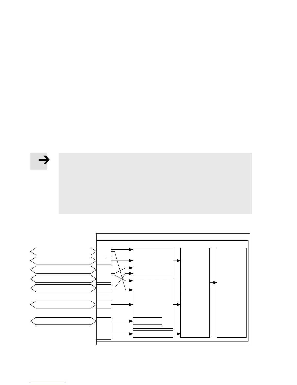
Activating the homing mode via fieldbus/digital inputs
X4
CMMS/CMMD
CANOpen
PROFIBUS DP
RS485
Digital inputs
Fieldbus
Control section
X1
X1.1
X1.2
EXT
EXT1
X5
DeviceNet
Inputs
DriveBus
Record
selection/
Positioning
record: 0
Direct mode
Bit 0…5
Position
control
Controller-
internal
positioning
control
Limit switch 0/1
RS232
FCT
X5
Fig. 6.21 Overview: Activating the homing mode via fieldbus and digital inputs

 Loading...


