2Interfaces
40 Festo – GDCP-CMMS/D-FW-EN – 1404NH – English
2.4 Control interfaces – operating modes – operational functions
The motor c ontroller can be operated through a number of interfaces. Various operating modes and
operational functions are available, dependent on the selected c ontrol interface and the device profile
(only for fieldbus). The control interfaces are permanently assigned to the connections. You can take
the possible combinations from the following overviews.
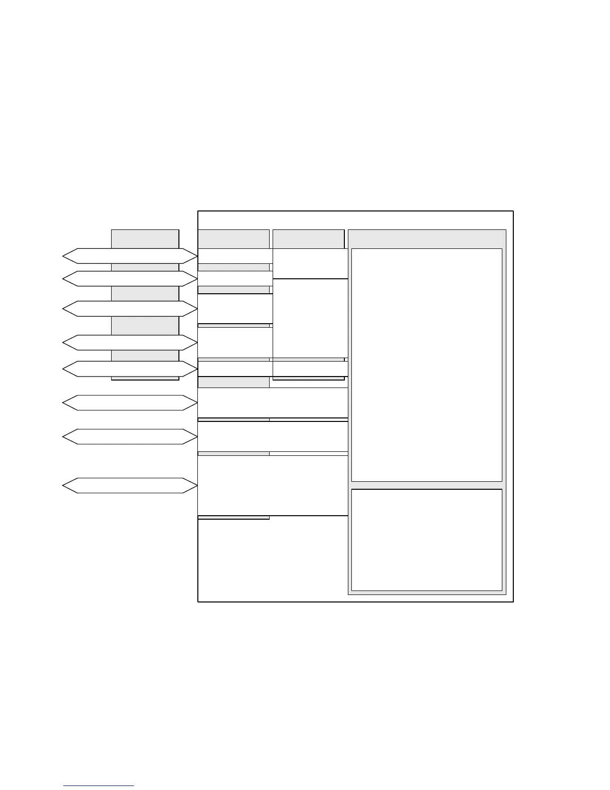
2.4.1 Overview: Control interfaces/connections/device pr ofiles /
operating modes/operational functions
X4
CMMS/CMMD
CANOpen
PROFIBUS DP
RS485
Control interfaces
Connections
EXT (CMMS)
EXT1 (CMMD)
X5
DriveBus
DeviceNet
Synchronisation
1)
CiA402
5)
FHPP
6)
CI
7)
Device profiles
Operational functions:
– Encoder emulation
– Flying measurement
– Analogue monitor
– Endless positioning
Operating modes:
– Positioning mode
•Directmode
• Individual record mode
• Record linking mode
• Interpolated positioning
mode
• Homing mode
•Jogmode
• Teach mode
– Speed mode
– Force/torque mode
– Synchronisation
X4
X1
2)
(CMMS)
X1.1/X1.2
2)
(CMMD)
Digital I/O modules
Analogue input/output
X1
3)
(CMMS)
X1.1/X1.2
3)
(CMMD)
Fieldbus
X1
2)
(CMMS)
X10
4)
(CMMS)
X1.1/X1.2
2)
(CMMD)
X10.1/X10.2
4)
(CMMD)
Operating modes/functions
EXT (CMMS)
EXT1 (CMMD)
1) Encoder input for the “ synchronisation” operating mode
2) HTL signal (high transistor logic): High signal = 24 V
3) Analogue input signal: ± 10 V,
analogue output signal: + 10 V
4) TTL signal (transistor-transistor logic): High signal = 5 V
5) CANopen device profile CiA 402
6) Festo handling and positioning profile (FHPP)
7) CAN-Interpreter
Fig. 2.13 Over view: Control interfaces/connections/device profiles/operating modes/operational
func tions

 Loading...


