4 Dimension reference system
Festo – GDCP-CMMS/D-FW-EN – 1404NH – Engli sh 75
4 Measuring system
4.1 Measuring system for electrical drives
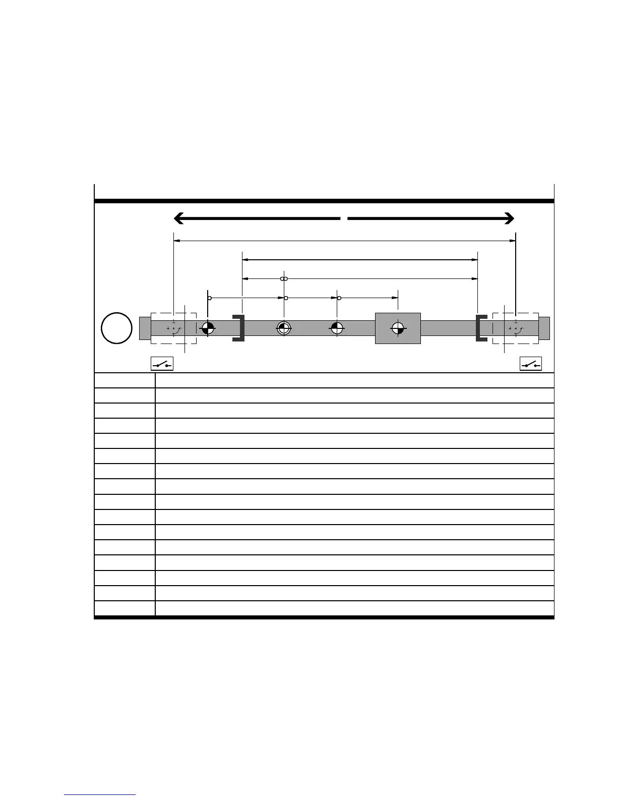
4.1.1 Measuring system for linear drives
Example: Homing method “limit switch”, negative direction
REF AZ
abc
PZ
de
TP/AP
SLP
SLN
Run positive (+)
LSN LSP
Run negative (–)
M
1
2
REF Homing point (reference point)
1)
AZ Axis zero point
1)
PZ Projec t zero point
SLN Negative software end position (SW limit negative)
SLP Positive software end position (SW limit positive)
LSN Limit switch (hardware) negative ( Limit switc h negative)
1)
LSP Limit switch (hardware) positive (Limit switch positive)
1)
SP Target position
AP Ac tual position1)
a Offset “axis zero point (AZ)”
b Offset “project zero point ( PZ)”
c Offset “target/actual position ( TP/AP)”
d Offset “Software end position negative (SLN)”
e Offset “Soft ware end position positive (SLP)”
1 Effective stroke
2 Working stroke (no hardware limit switches)
1) Additional information page 161.
Tab. 4.1 Measuring system for linear drives
Additional information CD-ROM: Documentation “CMMS-AS_de.pdf/CMMS-ST_de.pdf/CMMD-
A S _ de.pdf” or the Festo Configuration Tool ( FCT): Dynamic/static plug-in help.

 Loading...


