7 Speed mode and force/torque mode
Festo – GDCP-CMMS/D-FW-EN – 1404NH – Engli sh 189
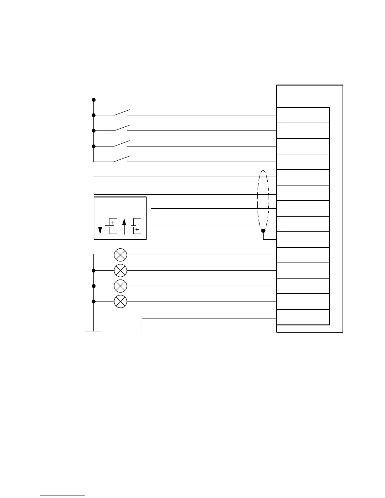
7.2.3 Connection: Analogue and digital I/O modules
The c onnection diagram shows the required digital inputs for the force/torque mode.
Analogue load ( AGN D), reference potential “reference
voltage output/analogue inputs”
24 V DC
Controller enable (DIN5)
Output stage enable (DIN4)
Limitswitch0(DIN6)
1)
Limitswitch1(DIN7)
1)
Common error (D OUT3)
2)
Analogue input, differential (#AIN0)
Screening (SGN D)
Controller ready for operation (DOUT 0)
Motion complete ( DOUT1)
2)
Star t confirmed (DOUT2)
2)
CMMS/CMMD
X1/X1.1/X1.2
12
9
21
22
10
14
2
15
1
24
13
25
Setpoint value:
-10…+10 V
Load “DIN/DOUT” (GND 24 V)
6
4
Referenc e voltage output (VREF
OUT
), +10 V DC
Analogue input, differential (#AIN0)
1) The limit switches are set by default to N/C contact (configuration over FCT)
2) Default setting, freely configurable in the Festo Configuration Tool (FCT).
Fig. 7.7 Connection: Analogue and digital inputs/outputs

 Loading...


