9 Opera tional functions
Festo – GDCP-CMMS/D-FW-EN – 1404NH – Engli sh 199
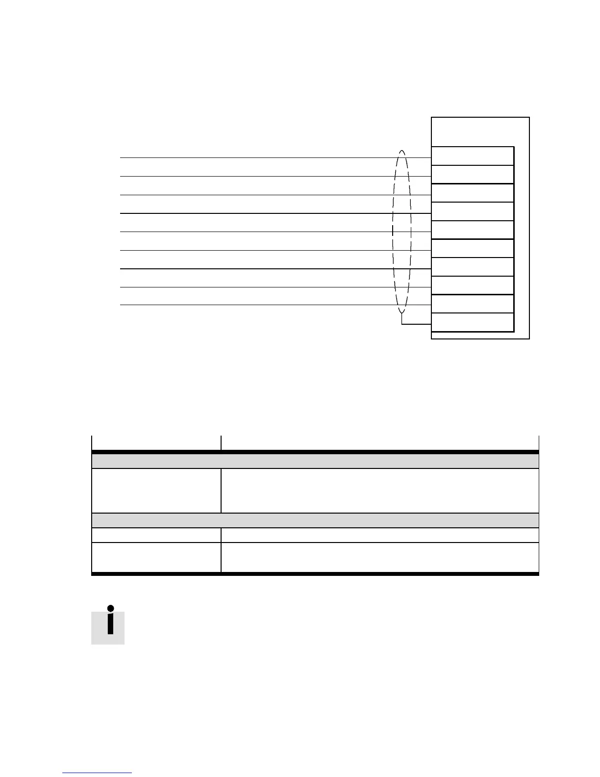
9.1 .2 Connection: Encoder output (5 V)
The connection diagram shows the digital outputs for encoder emulation.
CMMS/CMMD
X10/X10.1/X10.2
1
2
3
6
7
8
Incremental signal
A
#N
B
#A
N
#B
4
1)
5
“Incremental signal” load (GND)
Auxiliary power supply 5 V DC ± 5 % / max. 100 mA
Housing
Screening (SGN D)
9
1)
Load “auxiliary power supply” (GND)
1) Pin “4” and “9” are connected internally.
Fig. 9.2 Connection: Encoder output, 5 V
9.1.3 Configure/parameter ise encoder emulation
The following settings can be configured and parameterised in the Festo Configuration Tool (FCT):
Settings
Description
Encoder Data
Number of Increments Value, number of inc rements per revolution ( 360°).
The number of increments specifies the number of emulated incre-
mental signals “A/#A/B/#B” per revolution.
Options
Ignore Zero Pulse The zero pulse signals “N/#N” are not passed on to the slave device.
Reversal of Rotation Direc-
tion
The phase displacement of the signals “A/#A” and “B/#B” is rotat ed
by 180°.
Tab. 9.1 Configure/parameterise encoder emulation
To avoid rounding errors, the number of lines per revolution should contain the factor 2
n
.
(1,2,4,8,...2048).

 Loading...


