6 Positioning mode
Festo – GDCP-CMMS/D-FW-EN – 1404NH – Engli sh 171
6.9 Jog mode
6.9.1 Function: Jog mode
The drive can be manually mov ed in the jog mode to any position within the parameterised limits (e.g.
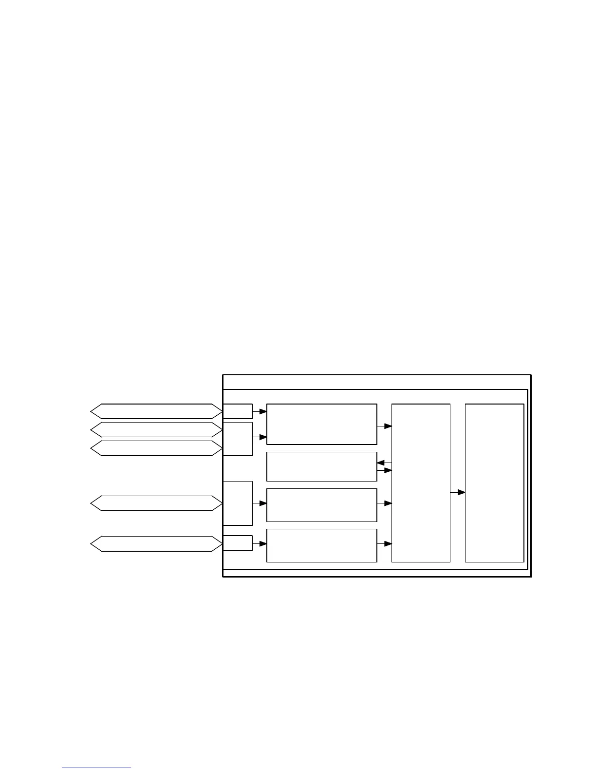
limit switches). The motor controller can be controlled in the jog mo de directly via the active fieldbus
(CANopen/PROFIBUS DP/DeviceNet), the digital inputs (mode 1 page 49) or the parameter inter-
face (RS232, Festo Configuration Tool ( FCT)). Through the direct application of the fieldbus, the digital
inputs “Jog+ ( DIN10)/Jog– (DIN11)” or the Festo Configuration Tool (FCT) “Jog<</Jog>>”, the controller-
internal positioning control receives the travel direction for the jog mode. The controller-internal posi-
tioning controller calculates the jog curve from the jog parameters and transfers the position setpoint
values cyclically to the position control. The drive first runs at creep speed in the jog mode. If, after
expiration of the creep duration, c ontrol is still active, the drive ac c elerates to jog speed in order to
travel through large paths quickly. Jog mode is quit with the falling edge of the jog signal.
This operating mode c an be used in the following applications:
– Approaching the teac h position
– Drive free running (e.g. after a malfunction)
– Manual running (manually operated feed)
The jog parameters can be parameterised via fieldbus or Festo Configuration Tool ( FCT).
Activating the jog mode via fieldbus /FCT/digital inputs
X4
CMMS/CMMD
CANOpen
PROFIBUS DP
Digital inputs
Fieldbus
Control section
X1
X1.1
X1.2
EXT
EXT1
DeviceNet
Inputs
Direct mode
Jog Parameters
Jog+
Jog–
X5
RS232
FCT
Jog>> (+)
Jog<< (–)
Position
control
Controller-
internal
positioning
control
Fig. 6.27 Over view: Activating the jog mode via fieldbus/FCT/digital inputs

 Loading...


