8 Synchronisation
Festo – GDCP-CMMS/D-FW-EN – 1404NH – Engli sh 195
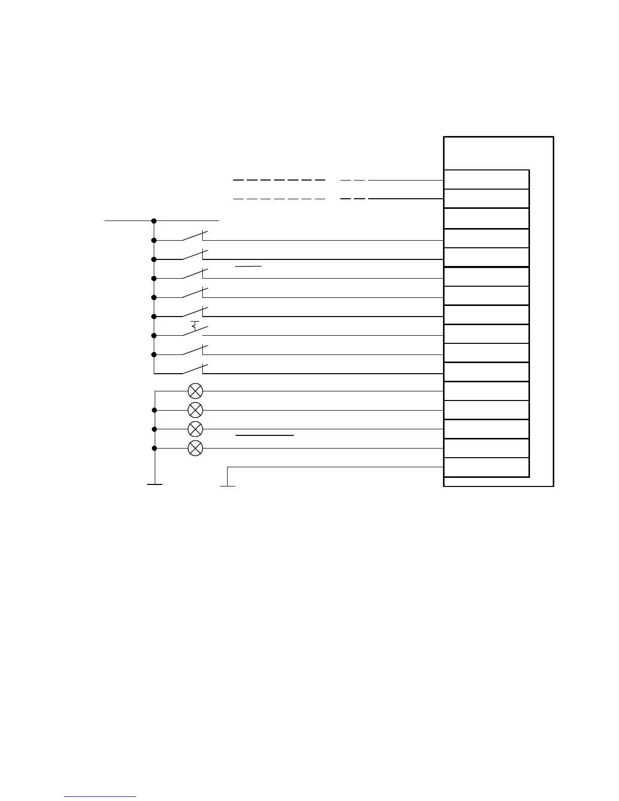
8.1.3 Connection: Digital inputs/outputs (24 V)
The connection diagram shows the required digital inputs for synchronisation via the connec-
tion [X1][X1.1/X1.2] .
Stop (DIN13)
24 V DC
Controller enable (DIN5)
Output stage enable (DIN4)
Common error (D OUT3)
2)
Controller ready for operation (DOUT 0)
Motion complete ( DOUT1)
2)
Setpoint position reached (DOUT2)
2)
CMMS/CMMD
12
9
21
15
11
2
23
24
13
25
Limitswitch1(DIN7)
1)
10
22
Limitswitch0(DIN6)
1)
Mode bit 0 (DIN12)
Mode bit 1 (DIN9)
Start sync (DI N)
6
X1/X1.1/X1.2
20
8
Pulse/direction
signal
Forward/reverse
signal
CLK (DIN2)
DI R (DIN3)
CW (DIN2)
CCW (DIN3)
...
Load “DIN/DOUT” (GND 24 V)
Mode 3
1) The limit switches are set by default to N/C contact (configuration over FCT)
2) Default setting, freely configurable in the Festo Configuration Tool (FCT).
Fig. 8.3 Connection: Digital inputs/outputs (24 V)

 Loading...


