2Interfaces
Festo – GDCP-CMMS/D-FW-EN – 1404NH – Engli sh 27
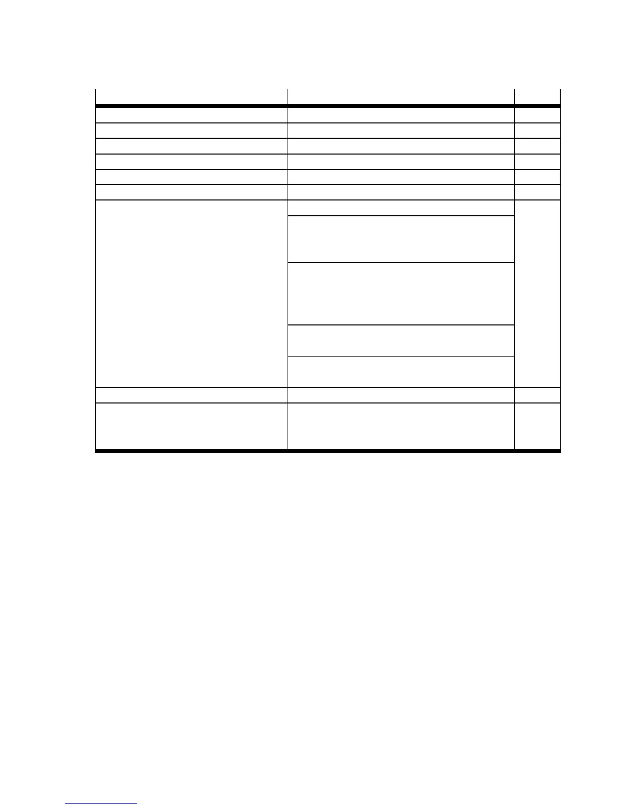
Interface Function Page
1 Mains supply
2 Power switch
3 Fuse “control section” Application-dependent
4 Fuse “power section” Application-dependent
5 Power supply unit “power section” Output voltage: 24/48 V DC
6 Power supply unit “control section” Output voltage: 24 V DC
7 Motor controller CMMS-ST-C8-7-G2 Protective earthing “ (housing) 12
Power supply [X9]
– Power section: 24/48 V DC (ZK+/0 V)
– Control section: 24 V DC ( 24 V/0 V)
Motor interfaces [X6]
– Motor string (A/#A/B/#B)
– Holding brake ( BR+ /BR–)
– Motor temperature sensor (MT+/MT–)
Motor encoder [ X2]
– Incremental signals (A/#A/B/#B/N/#N)
Terminal “motor cable screening GND”
(connec ted with protective earthing “)
8 Motor encoder
1)
(closed loop) Incremental signals (A/#A/B/#B/N/#N) 12
9 Stepper motor EMMS-ST/MTR-ST – Motor string (A/#A/B/#B)
– Holding brake ( BR+ /BR–)
– Motor temperature sensor (MT+/MT–)
12
1) If the stepper motor is configured without a motor encoder in the Festo Configuration Tool (FCT), the motor controller is automatic-
ally operated in an open control circuit (open loop).
Tab. 2.6 Overview: Po wer supply, motor and motor encoder interfaces

 Loading...


