3 Control interfaces
Festo – GDCP-CMMS/D-FW-EN – 1404NH – Engli sh 51
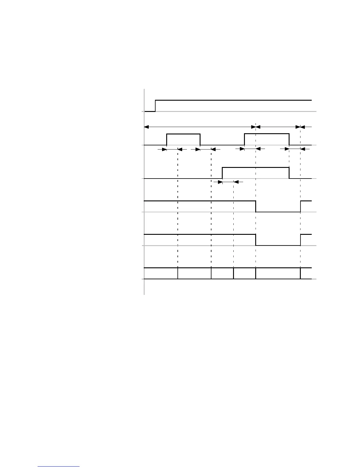
Timing diagra m: Selecting the operating mode/mode via digital input signals
The timing diagram shows the dependency of the four operating modes “Individual record (Mode 0)/
Jogging and teaching ( Mode 1)/Record linking (Mode 2)/Synchronisation (Mode 3)” on the digital input
signals “Mode bit 0/Mode bit 1”.
Mode bit 0
(DIN12)[X1.2]
Mode bit 1
(DIN9)[X1.11]
Motion Complete
1)
Standstill reached
2)
(DOUT1)[X1.12]
Controller ready for operation
(DOUT0)[X1.24]
Individual record, mode 0
Jog/teach, mode 1
Record linking, mode 2
Synchronisation, mode 3
Star t confirmed
1)
Position synchronous
2)
(DOUT2)[X1.25]
0012
30
t1
t1
t1t1
t1
Mode 0…2 Mode 3
1) Only active for mode 0…2
2) Only active for mode 3
t1 ≤ 5ms
Fig. 3.4 Timing diagram: Selecting the operating mode/mode via digital input signals “Mode bit 0/1”

 Loading...


