3 Control interfaces
Festo – GDCP-CMMS/D-FW-EN – 1404NH – Engli sh 55
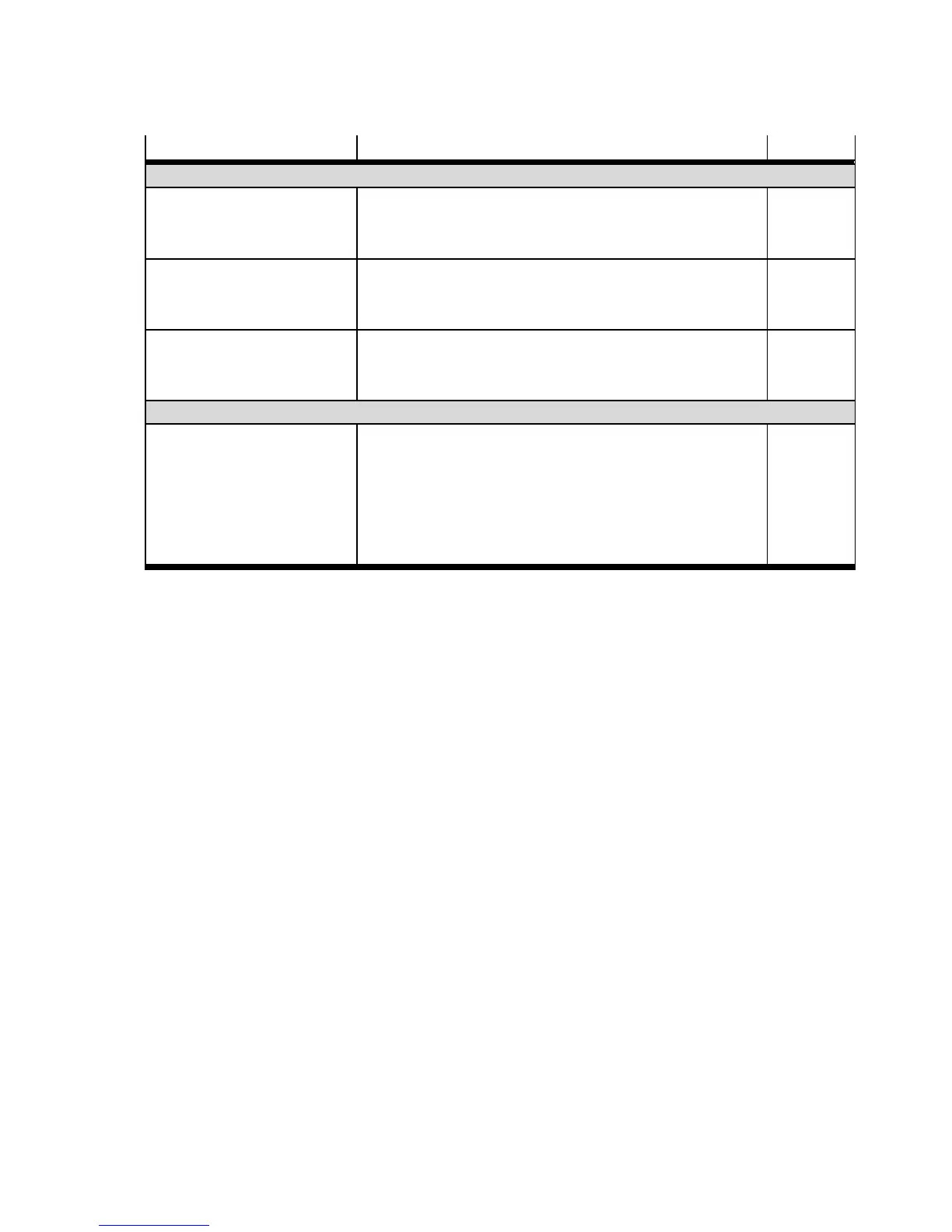
Signal SignalDescription
Synchronisation (mode 3)
Start Synchronisation
(DIN8)
[X1.23]/[X1.1.23/X1.2.23]
Signal for star ting synchronisation page 196.
– With the high signal, synchronisation is started.
– With the low signal, synchronisation is stopped.
high
active
CLK/CW_24
(DIN2)
[X1.20]/[X1.1.20/X1.2.20]
Encoder signals for synchronising the motor controller.
– CLK: Pulse signal
– CW: Forward signal
configur-
able
DI R/CCW_24
(DIN3)
[X1.8]/[X1.1.8/X1.2.8]
Encoder signals for synchronising the motor controller.
–DIR:Directionsignal
– CCW: Reverse signal
configur-
able
Flying measurement
Sampling
(DIN9)
[X1.11]/[X1.1.11/X1.2.11]
Signal for storing the actual position page 200.
– With the configured edge of the sample signal, the
current ac tual position of the drive is taken over into
the sample memory. The higher-order c ontroller can
interrogate the last stored actual position via the act-
ive fieldbus.
configur-
able edge
trigger
Tab. 3.3 Overview: D igital input signals

 Loading...


