18 FCP-300/FCP-300ECS Manual — P/N LS10145-002FK-E:A 3/12/2021
Installation Requirements Wiring Specifications
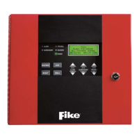
Figure 3.1 Wire Routing Example for FCP-300
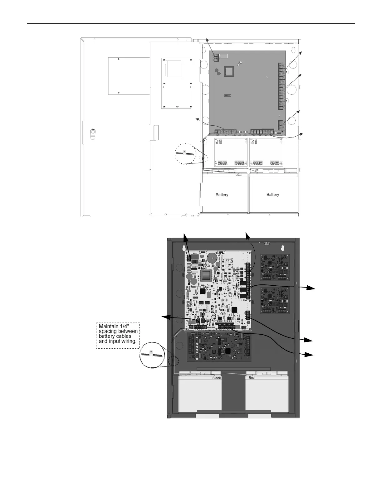
Figure 3.2 Wire Routing the FCP-300/ECS Example
Relay Outputs
NAC/Aux Power
Outputs
SBUS Devices
Phone Lines
SLC IN/OUT
AC Power
Input
Note: 1/4” spacing must be
maintained between each
of these circuit types; as well
as between power-limited
and non-power-limited circuits.
SLC
Phone Lines
AC Power Input
SBUS
Devices
In/Out
Relay Outputs
NAC/Aux Power
Outputs
Battery
Battery
Note: 1/4” spacing must be
maintained between each of
these circuit types, and
between the power-limited
and non-power-limited
circuits.