58 FCP-300/FCP-300ECS Manual — P/N LS10145-002FK-E:A 3/12/2021
Networking FIK-NIC Wiring Options
5.3.2 FIK-NIC Installation
The FIK-NIC is designed to mount on one of the SLC standoff sets, inside the cabinet or remotely using the accessory cabinet.
Use the following steps to properly mount the FIK-NIC inside the FCP-300/ECS.
1. Place the FIK-NIC on one of the SLC expander standoff sets.
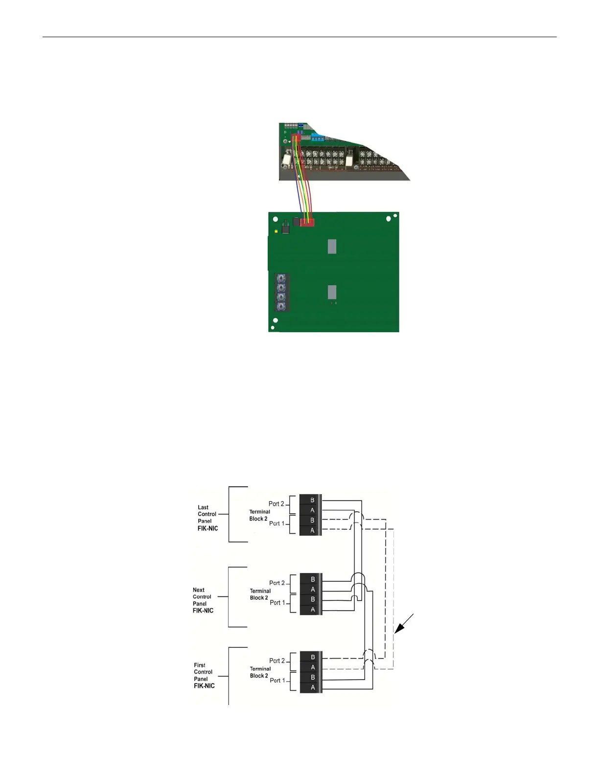
2. Use the 6-pin cable included with FIK-NIC to connect the FCP-300/ECS to the FIK-NIC. Connect the FIK-NIC to the pin
connector on the control panel labeled Data Network. See Figure 5.6.
Figure 5.6 Panel to FIK-NIC connection
3. Each FIK-NIC has the ability to monitor for earth ground faults on the twisted pairs connected to Port 1 of its terminal
block TB2. Earth fault detection for any wiring at Port 2 of TB2 is done at the next/previous FIK-NIC due to these wiring
connections being connected to Port 1 of TB2 at the next/previous FIK-NIC.
4. Unused optic ports on fiber loop modules must have their dust caps placed on the port.
5. Based on the type of data medium chosen, run the twisted-pair wiring/fiber-optic cable to the next FIK-NIC using a Class
B or Class A wiring method. A combination of both medium types can be used. See Figure 5.7, Figure 5.8, Figure 5.9,
and Figure 5.10 for the FIK-NIC wiring examples.
To mount the FIK-NIC remotely:
Follow the steps above, except the 6-pin cable, that runs from the FIK-NIC to the FCP-300 and must be run in conduit. See
Figure 5.1.
Unshielded Twisted Pair Wiring between Multiple Panels
Unshielded twisted pair wiring between multiple panels is shown in Figure 5.7. Class A wiring is shown with a dotted line..
Figure 5.7 Twisted Pair Wiring Configuration