SBUS Wiring Control Panel Installation
FCP-300/FCP-300ECS Manual — P/N LS10145-002FK-E:A 3/12/2021 29
Wiring Distance Calculation Example:
Suppose a System is configured with the following SBUS modules:
• 2 - Module FIK-RA1000 Fire Annunciator
• 1 - FIK-5496 NAC Expander
• 1 - FIK-5865 LED Fire Annunciator
• 1 - FIK-5824 Serial/Parallel Printer Interface Module
The total worst case current is calculated as follows:
Using this value, and referring to the Wiring Distance table, it can be found that the available options are as follows:
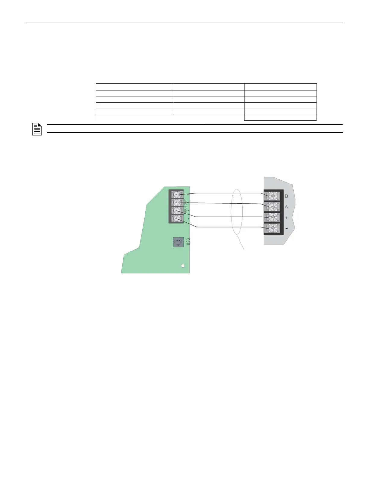
4.4.2 Wiring Configurations
Figure 4.8 illustrates the SBUS, Class B configuration.
Figure 4.8 SBUS Class B Wiring
Current Draw Amps Amps
FIK-RA1000 Current Draw = 2 x .100 amps = .200 amps
FIK-5496 Current Draw = 1 x .010 amps = .010 amps
FIK-5865 Current Draw = 1 x .200 amps = .200 amps
FIK-5824 Current Draw = 1 x .040 amps = .040 amps
Total Worst Case Current Draw = .450 amps
NOTE: For assistance with the SBUS calculation, refer to www.fike.com.
• 370 feet maximum using 22 Gauge wire • 1493 feet maximum using 16 Gauge wire
• 938 feet maximum using 18 Gauge wire • 2362 feet maximum using 14 Gauge wire