FCP-300/FCP-300ECS Manual — P/N LS10145-002FK-E:A 3/12/2021 55
Section 5: Networking
5.1 Network System Hardware Features
The FCP-300/ECS panels can be networked to create a virtual System that is larger than 300 addressable points. Each additional FCP-
300/ECS provides another 300 addressable points to the network total. For example, a network of 32 FCP-300/ECS panels provides a
maximum addressable point capacity of 9,600 points (300 x 32 = 9,600).
5.1.1 Networked Sites
A networked site is a logical group of panels that operate as though the logical group is one large control panel. Each building is referred
to as a “site.” All panels in a site operate as a single panel. The control functions such as, Reset, Silence and Alarm activation operate
across the entire site. There can be one or more logical sites within a networked System. The maximum number of sites within a network
System is limited to 32 panels in the network with each site comprised of only one panel.
5.1.2 Wiring Options/Requirements to Connect Networked Panels
1. Fiber-Optic Single Mode - Use the FIK-NIC and FIK-FSL for up to 30dB loss of signal separation. The FIK-FSL connects to the
network using 9/125 micron single-mode fiber.
2. Fiber-Optic Multi-Mode - Use the FIK-NIC and FIK-FML for up to 8dB loss of signal separation. The FIK-FML connects to the
network using 62.5/125 micron multi-mode fiber.
3. Twisted-Pair Copper Wire - must use the FIK-NIC to provide up to 3,000 feet of separation.
All methods of the panel connectivity can be used within the same networked System. The network architecture provides true peer-to-
peer capability allowing the network survivability for all hardware that remains operational in the event of the partial System failure.
5.2 Network Wiring
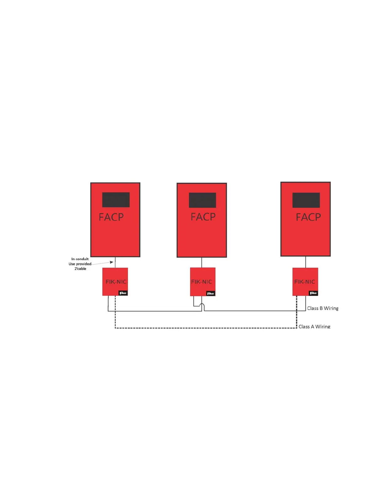
When you network a group of FCP-300/ECS you must use the FIK-NIC to link the panels together. See Figure 5.1 and Figure 5.2, for the
Internal mounting or external mounting of the FIK-NIC options.
Figure 5.1 External FIK-NIC Wiring Option