On-Board Relays (Conventional) Control Panel Installation
FCP-300/FCP-300ECS Manual — P/N LS10145-002FK-E:A 3/12/2021 49
4.15 On-Board Relays (Conventional)
The control panel has two built-in programmable relays and a built-in trouble relay. All relays are Form C rated at 2.5 A @ 24
VDC (resistive).
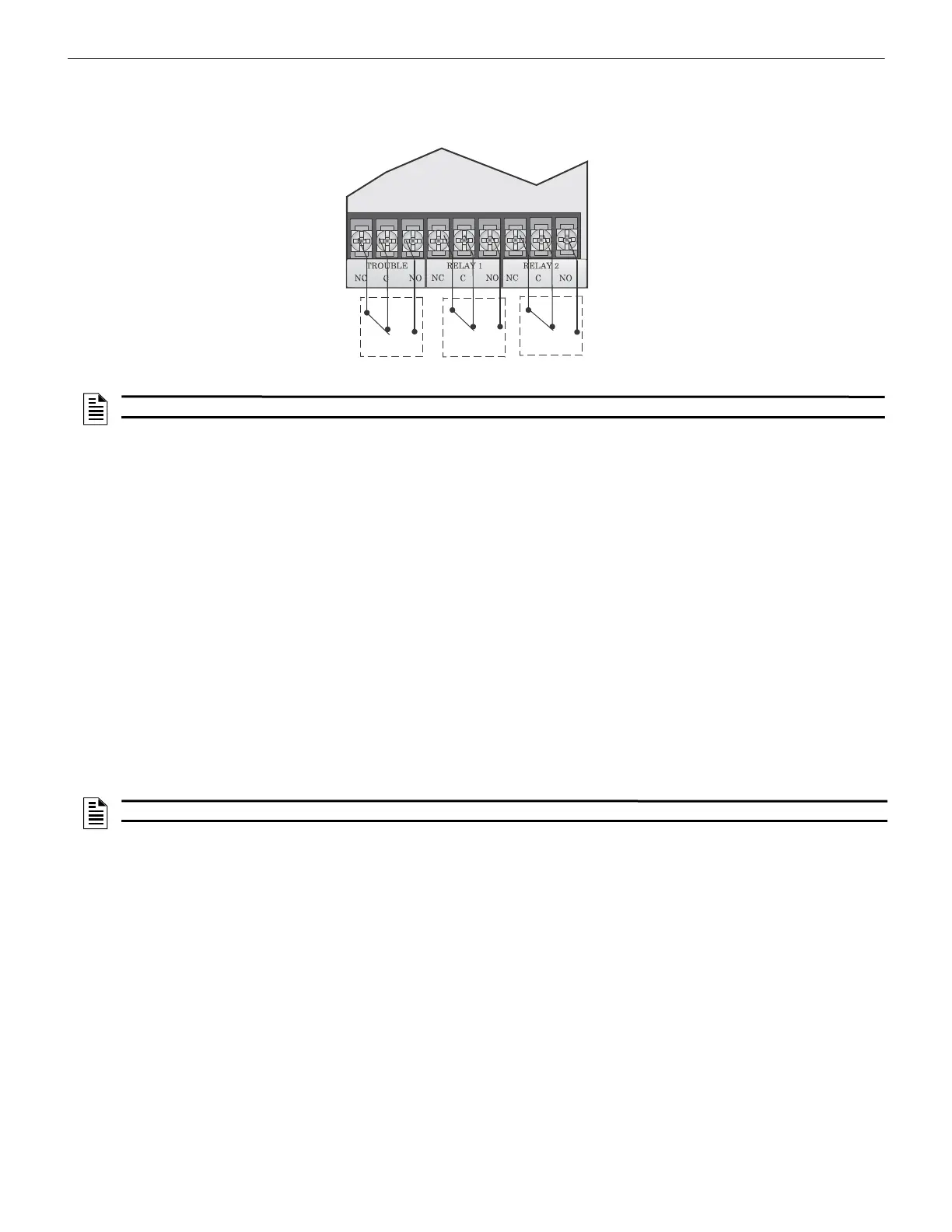
Figure 4.43 Location of Conventional Relay Circuits
4.15.1 Trouble Relay
The control panel has a dedicated common Form C trouble relay built into terminals labeled TROUBLE. The relay provides a
normally open and a normally closed contact. The trouble relay will deactivate under any trouble condition.
4.15.2 Programmable Relays
The control panel has two Form C programmable relays built into the terminals labeled, RELAY 1 and RELAY 2. Each relay
provides a normally open and a normally closed contact.
To install one or two programmable relays, follow these steps.
1. Wire Relay 1 and/or Relay 2 as needed for your application. See Figure 4.43 for the location of the relay terminals.
2. Configure the relay through programming (see section 9.5).
4.16 Remote Station Applications
4.16.1 Keltron Model 3158 Installation
The control panel is compatible with the Keltron Model 3158 that is used for the direct connection to a Keltron receiver. The
3158 reports alarms, supervisories, and troubles.
The steps for connecting the 3158 to the control panel. Refer to the 3158 Installation Instructions for complete information.
1. Wire the 3158 to the control panel as shown in the connection list and Figure 4.44.
2. Wire the 3158 within 20 feet of the control panel. Wiring must be enclosed in conduit.
3. Program the control panel Relay 2 for alarm.
4. Program the NAC circuit 2 for alarm.
5. Program the NAC circuit 1 for supervisory non latching.
Connect to Power
Limited Sources only
NOTE: The N.C. contact is the relay contact that is closed when the panel has power and there are no alarm or trouble conditions.
NOTE: The NACs must be programmed for continuous and non-silencing.