Mapping Overview Programming Overview
FCP-300/FCP-300ECS Manual — P/N LS10145-002FK-E:A 3/12/2021 81
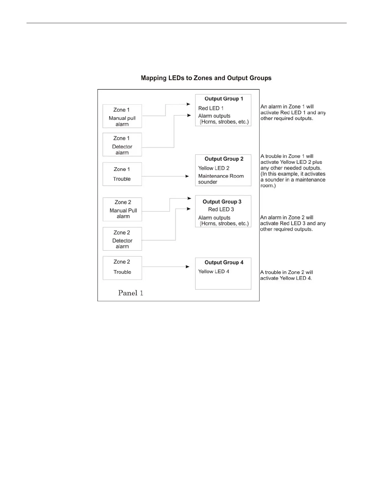
8.2.4 Mapping LED Points
Figure 8.7 is a simple example showing how the LED points are mapped to the zones and the output groups. Typically, you
would create the following two output groups for each zone:
The LED points are available when the Models FIK-5865-3/4 and/or FIK-5880 are used with the System).
Figure 8.7 Example of LED Points Mapped to Output Groups
(applies to Models FIK-5865-3/4 and FIK-5880)
• one output group for alarms • one output group for troubles