Scope/Meter Mode
Triggering on a Waveform
2
2-17
Triggering on a Waveform
Triggering tells the test tool when to begin displaying the
waveform. You can select which input signal should be
used, on which edge this should occur, and you can define
the condition for a new update of the waveform. You can
setup the test tool to trigger on video signals.
The bottom line of the waveform area identifies the trigger
parameters being used. Trigger icons on the screen
indicate the trigger level and slope. (See Figure 2-15.)
Note:
For 3 phase power measurements the trigger
settings are fixed.
Setting Trigger Level and Slope
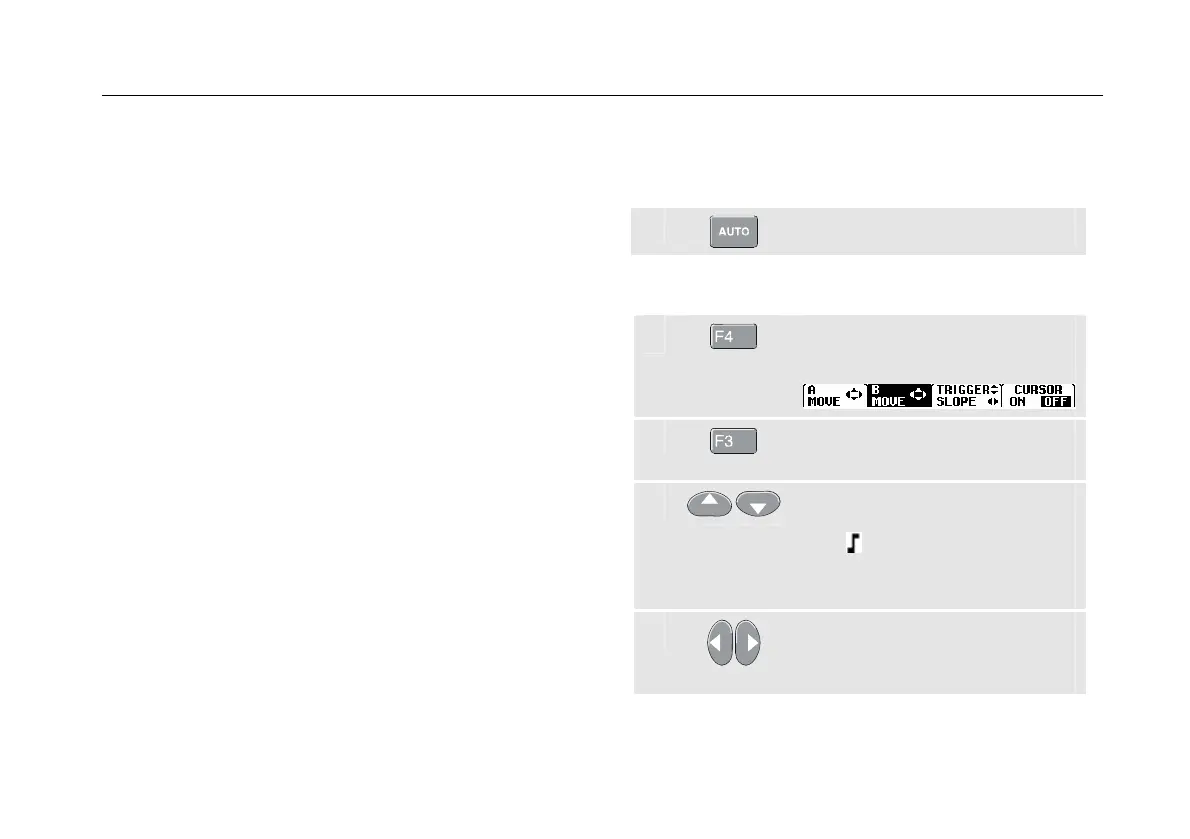
For quick operation, use the AUTO SET key to
automatically trigger on nearly all signals.
c
Perform an AUTO SET.
To optimize trigger level and slope manually, do the
following:
c
Press until you have left any open
menu.
d
Enable the arrow keys for Trigger
Level and Slope adjustment.
e
Adjust the Trigger Level
continuously. Observe the trigger
icon on the second time
division line indicates the trigger
level.
f
Trigger on either positive Slope or
negative Slope of the chosen
waveform.