Scope/Meter Mode
Triggering on a Waveform
2
2-19
j
Accept all trigger selections and
return to normal measurement.
Note
Setting the automatic triggering to >1Hz will slow
down the auto range.
TRIG:A appears in gray text on bottom of the screen when
no trigger is found.
Note
Gray text in a menu or button bar indicates that
the function is disabled or the status is not valid.
FREE RUN: the test tool automatically updates the trace
even if there are no triggers.
ON TRIG.: the screen is updated only when valid
triggers occur.
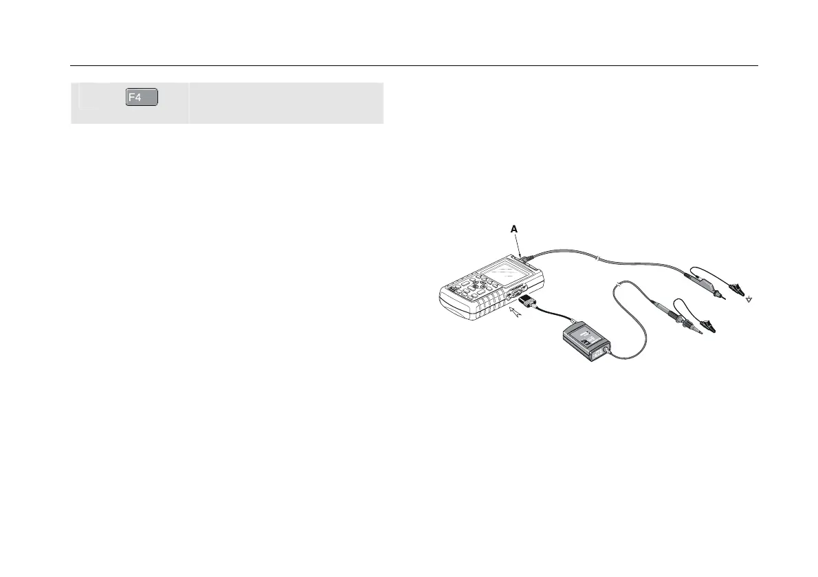
Isolated Triggering
Use the optically isolated trigger probe (ITP120, optional)
to trigger on an external source, and to isolate the test tool
from a trigger waveform. See Figure 2-16.
To choose the isolated trigger probe, select ‘EXT’ in point
e of the previous example. Trigger level is fixed and is
TTL compatible.
Figure 2-16. Isolated Triggering