5320A
Users Manual
6-4
Measurement Input Fuses
The Amps (A) terminal of the METER input, the HI terminal of the OUPUT terminals,
and the L terminal or the RCD terminals are protected by fuses at the rear of the
Calibrator.
To replace these fuses:
1. Unplug all connections to the front panel of the Calibrator.
2. Unplug the power cord from the Calibrator.
3. Locate the fuse holder for the function on the rear panel of the Calibrator (see Table
3-2, item 3).
4. Using a flat-blade screwdriver in the slot on the end of the fuse holder, unscrew the
fuse holder.
5. Replace the fuse with one rated for the selected function. See Table 6-2.
6. Reinsert the fuse holder and screw it into the socket.
W Caution
To avoid damaging the Calibrator, use only the fuse specified
for each of the measurement inputs.
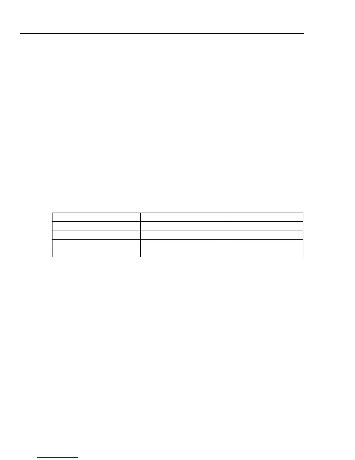
Table 6-2. Measurement Input Fuses
Input Fuse Fluke Part No.
RCD F3.15L250V (5 x 20 mm) 2743508
Leakage Current F100mL150V (5 x 20 mm) 2743513
Meter T20L500V (6.3 x 32 mm) 2743536
Loop/Line Impedance T4L250V (6.3 x 32 mm) 2743524
Cleaning the Air Filter
W Caution
Damage caused by overheating may occur if the area around
the fan is restricted, the intake air is too warm, or the air filter
becomes clogged.
The air filter must be removed and cleaned at least every 30 days, or more frequently if
the calibrator is operated in a dusty environment. The air filter is accessible from the rear
panel of the Calibrator.
To clean the air filter, proceed as follows:
1. Unplug all connections to the front panel of the Calibrator.
2. Unplug the power cord from the Calibrator.
3. Remove the filter by grasping the outside edges of the filter and pulling straight out.
4. Remove the filter element from the filter frame.
5. Clean the filter by washing it in soapy water. Rinse and dry the filter element
thoroughly before reinstalling.
6. Reinstall the filter element into the filter frame.
7. Snap the filter frame back on to the fan housing.