Calibrating Instruments
Setting the High Resistance Source Output 4
4-5
Note
Before adjusting the value, make sure the current generated by the UUT
will not exceed the maximum allowed value.
With the output connected, you can adjust the resistance value with the keyboard, cursor
keys or rotary knob. Any new values set using the front panel take approximately 500 ms
to appear on the output terminals. If during the adjustment the current or voltage exceeds
acceptable limits, the output terminals will be disconnected and an error message
displayed. Should the set value exceed the upper range limit or lower range limit, the
Calibrator displays “Value too high” or “Value too low”, respectively.
To change between 2-wire and 4-wire operation:
1. Press the Mode softkey.
2. Using the cursor keys or rotary knob, move the cursor to Resistance 2-Wire or
Resistance 4-Wire and either press the Select softkey or press in on the rotary
knob.
2-Wire or 4-Wire will be displayed next to the resistance value in the OUTPUT area
of the display.
To switch between grounded and ungrounded output:
1. Press the Setup softkey.
2. Using the cursor keys or rotary knob, highlight Low resistance source and either
press the Select softkey or press in on the rotary knob.
3. Using the cursor keys or rotary knob, highlight Low resistance source GND and
either press the Select softkey or press in on the rotary knob.
4. Using the cursor keys or rotary knob, highlight either GND On or GND Off and
either press the Select softkey or press in on the rotary knob.
5. Return to the main display by pressing the EXIT softkey repeatedly.
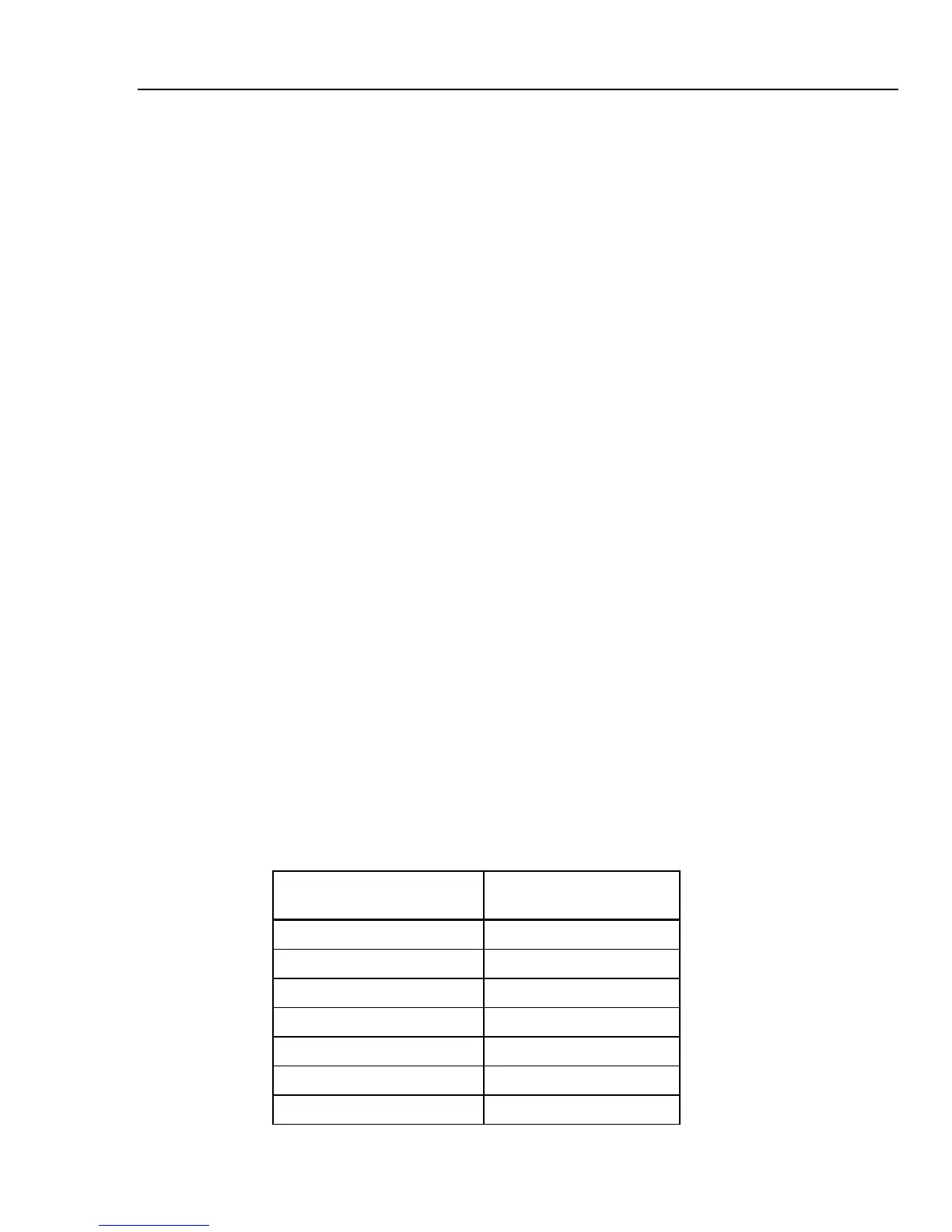
Setting the High Resistance Source Output
The calibrator’s High Resistance Source function is capable of presenting a resistance in
the range listed in Table 4-2 on its output terminals. The maximum acceptable voltage on
this resistance is dependent on the selected range and is also listed in Table 4-2.
Table 4-2. High Resistance Ranges with Maximum Voltage Rating
Resistance range
Maximum applicable
voltage (AC+DC)PEAK
10.000 to 39.99 kΩ 55 V
40.00 to 99.99 kΩ 300 V
100.00 to 199.99 kΩ 800 V
200.0 to 999.9 kΩ 1,100 V
1.000 to 9.999 MΩ 1,100 V
10.000 to 99.99 MΩ 1,575 V
[1]
100.00 MΩ to 999.9 GΩ 1,575 V
[1]