5320A
Users Manual
4-26
8. Press Start on the UUT.
The Calibrator puts power line voltage on the RCD L and N terminals. When start is
pressed on the UUT, the UUT’s internal load is connected to the Calibrator’s connectors.
When the measured current reaches a value specified by the product of the nominal trip
current and the current multiplier, a timer is triggered. The timer starts at the first zero
crossing of the power line voltage before the trip current value was reached. When the
time in the timer matches the selected trip time, the output connectors are disconnected
and the measured values are displayed.
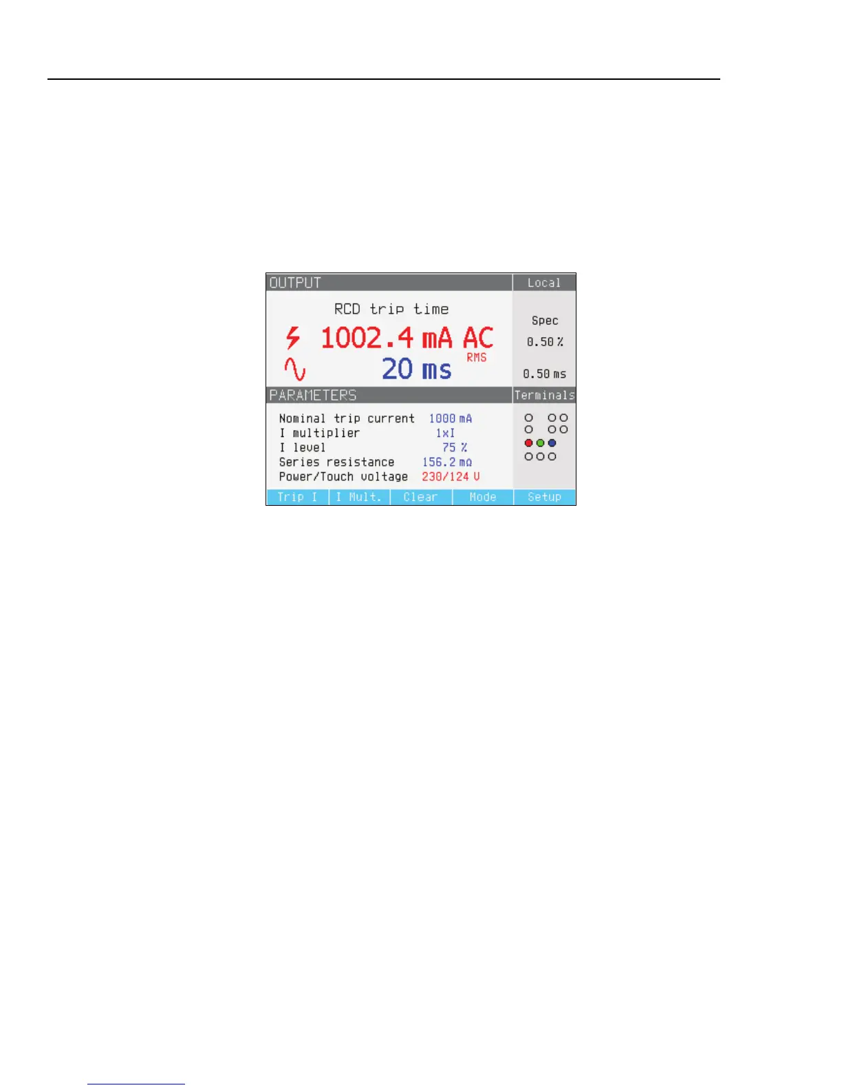
ehq027.bmp
Figure 4-17. RCD Trip Time Display
The Calibrator displays the following for an RCD trip time calibration:
• UUT test signal polarity is indicated with one of the following graphic icons:
I Positive symmetrical ac current (SYMP)
J Negative symmetrical ac current (SYMN)
W Positive pulse of dc current (POS)
X Negative pulse of dc current (NEG)
a dc current with positive polarity (DCP)
b dc current with negative polarity (DCN)
If the signal cannot be recognized, then “Not recognized” is displayed. When the trip
time is set to less than 20 ms, only positive and negative polarity are detected. If a
negative dc test current is detected, a “NEG” symbol is displayed. If a positive dc test
current is detected, a “POS” symbol is displayed. Phase is not displayed for dc
sensitive signals.
• Measured trip current as an rms value.
• Power/Touch voltage
Power Line Voltage
The Calibrator measures the power line voltage as a first step in the tripping procedure.
This voltage is measured after the output terminals are switched on.