5320A
Users Manual
1-12
Ground Bond Resistance Source
Range.................................................................25 mΩ to 1.8 kΩ
Resolution ......................................................... 16 discrete values
Minimum test voltage/current..........................10 V / 10 mA
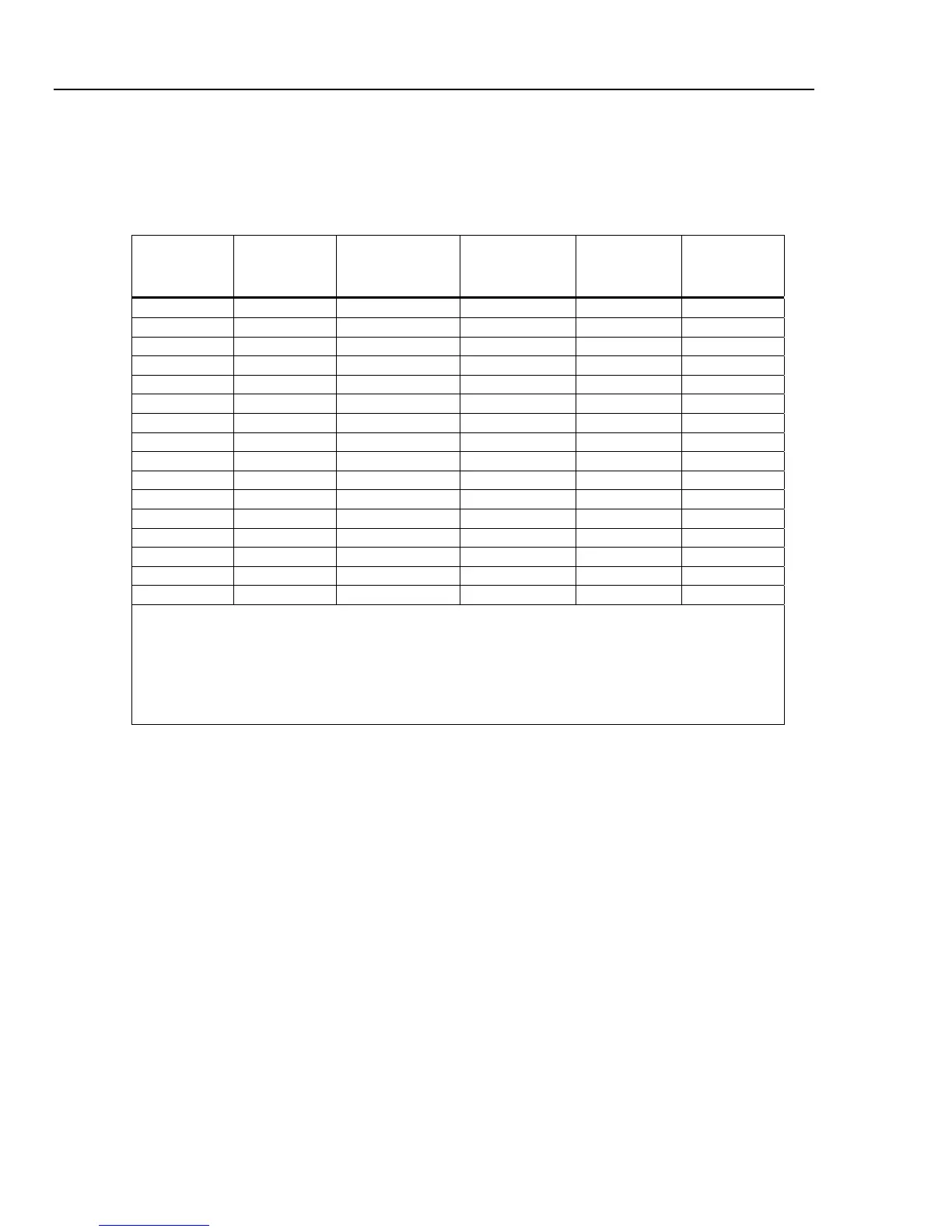
Uncertainty and Maximum Ratings
Nominal Value
Deviation from
Nominal Value
Absolute
Uncertainty of
Characterized Value
(tcal ±5 °C)
Maximum
Continuous Test
Current
ACrms or DC
[1]
Maximum Short-
term Test
Current
AC rms or DC
[2]
Test Current
Uncertainty
25 mΩ ±50 % ± 5 mΩ
30 A 40 A 1.5 % + 0.7 A
50 mΩ ±50 % ± 5 mΩ
28 A 40 A 1.5 % + 0.5 A
100 mΩ ±30 % ± 5 mΩ
25 A 40 A 1.5 % + 0.35 A
330 mΩ ±20 % ± 7 mΩ
14 A 40 A 1.5 % + 0.3 A
500 mΩ ±10 % ± 8 mΩ
10 A 40 A 1.5 % + 0.2 A
1 Ω ±10 % ± 10 mΩ
8 A 40 A 1.5 % + 150 mA
1.8 Ω ±10 % ± 18 mΩ
6 A 30 A 1.5 % + 100 mA
5 Ω ±10 % ± 30 mΩ
3.2 A 21 A 1.5 % + 70 mA
10 Ω ±10 % ± 60 mΩ
2.0 A 15 A 1.5 % + 50 mA
18 Ω ±10 % ± 100 mΩ
1.5 A 10 A 1.5 % + 30 mA
50 Ω ±10 % ± 300 mΩ
0.8 A 5.0 A 1.5 % + 20 mA
100 Ω ±10 % ± 500 mΩ
0.5 A 3.0 A 1.5 % + 10 mA
180 Ω ±10 % ± 1 Ω
0.25 A 1.35 A 1.5 % + 5 mA
500 Ω ±10 % ± 2.5 Ω
0.1 A 0.6 A 1.5 % + 3 mA
1 kΩ ±10 % ± 5 Ω
0.05 A 0.3 A 1.5 % + 2 mA
1.8 kΩ ±10 % ± 10 Ω
0.025 A 0.15 A 1.5 % + 2 mA
Notes:
[1] Test currents up to 30 % of maximum continuous test current can be applied to the Calibrator with no time limitation. Test
current between 30 % and 100 % of the maximum continuous test current can be applied to the Calibrator for a limited time.
Minimum period of full current load is 45 seconds. The Calibrator calculates the allowed time period and when exceeded,
the output connectors are disconnected.
[2] Maximum short term test current is defined as the rms value of halfwave or fullwave test current flowing through the UUT.
Maximum time of test is 200 ms. A time interval of 200 ms represents 10 full waves of power line voltage at 50 Hz and 12
full waves at 60 Hz.
Test Current Measurement
Range.................................................................0 to 40 A ac+ dc rms
Resolution ......................................................... 1 mA to 100 mA depending on resistance output and test current
Open Mode
Nominal resistance...........................................>100 kΩ
Maximum voltage.............................................. 50 V ac+dc rms
Test voltage range............................................ 0 to 50 V ac+dc rms
Resolution ......................................................... 1 V
Uncertainty ........................................................ 2 % + 2 V