Front-Panel Operation
Controlling the Calibrator 3
3-9
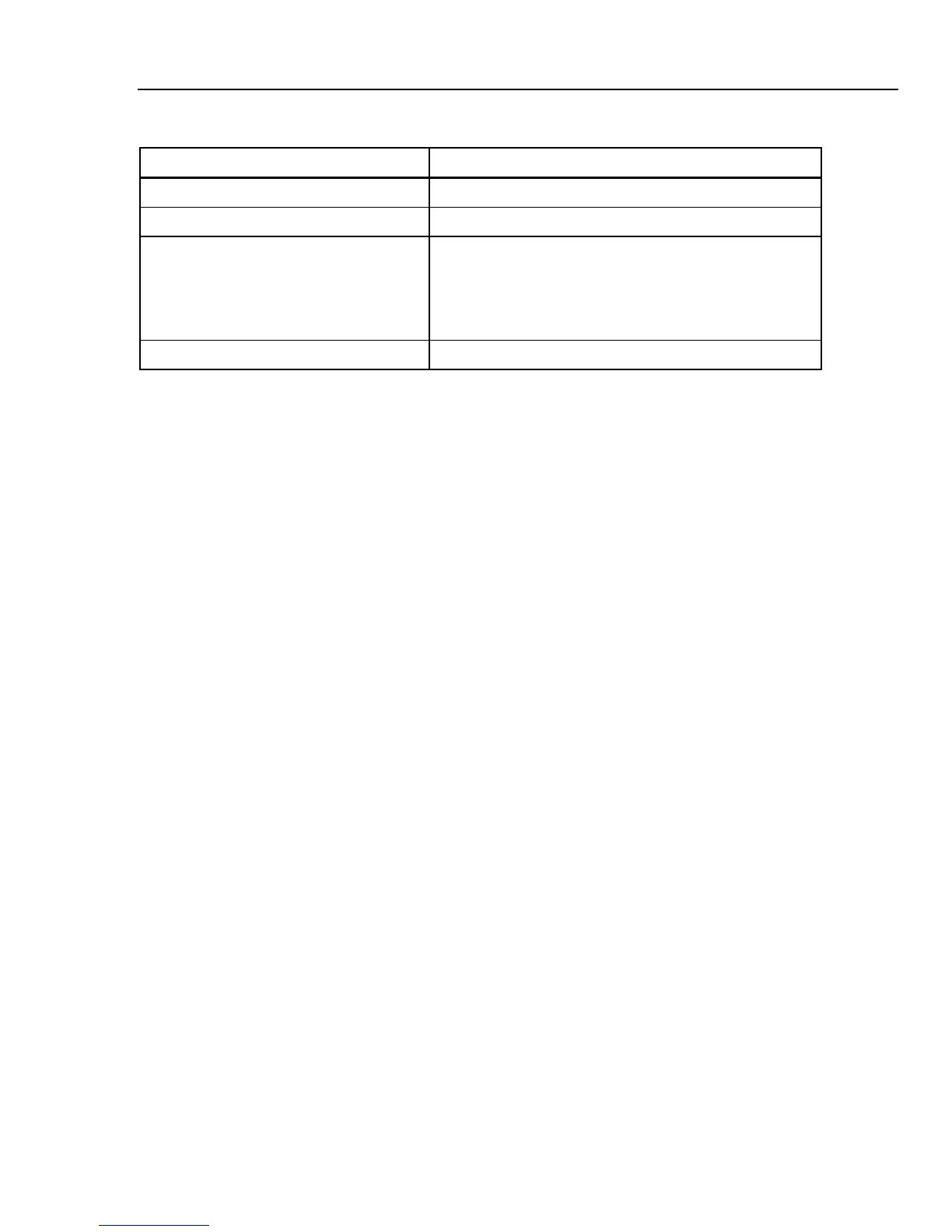
Table 3-3. Display Panel Features (cont.)
Item Description
C Softkey labels Displays the labels for the five soft keys below the display.
D Terminals Displays the active terminals for the selected function.
E Specifications Displays the accuracy of the output signal or measured
parameter. If the Calibrator is outputting two signals, two
accuracy specifications are displayed here. If the Calibrator is
not within specifications, BUSY is displayed instead of the
specification.
F Local or Remote Displays which of the two control modes is enabled.
Display Colors: A set of common rules are used to apply color to labels and values
appearing in the display.
1. Red denotes a value that is measured or scanned by the Calibrator (2.2 A in this
example).
2. Blue denotes a value or parameter that can be set or changed through the front-panel
keyboard or a setup function (1.025 mΩ in this example).
3. Black denotes fixed values, labels, notes or parameters which cannot be modified (8
A in this example).
4. White on a Blue field is always used for softkey labels.
Controlling the Calibrator
The following sections give an overview of basic Calibrator operation. More detailed use
is described in Chapter 4.
Selecting a Function
Once the Calibrator is powered on and the self-test has completed successfully, the
Calibrator sets itself to its reference state of Meter mode.
To change the Calibrator’s state:
1. Press the desired function key.
Whenever a different function is selected, the Calibrator uses the parameters that
were set the last time the function was used.
Note
Whenever the function changes, the Calibrator always switches to
STANDBY mode.
XWWarning
To avoid electric shock, always be sure the Calibrator and the
UUT are in STANDBY mode before removing or connecting
leads to the front-panel connectors.
2. Make the appropriate connections between the Calibrator and UUT. Refer to the
Terminals area of the display as a guide.