Calibrating Instruments
Introduction 4
4-3
Introduction
This chapter describes using the Calibrator’s functions for calibrating testers and meters.
It is assumed the reader is already familiar with the Calibrator’s controls, connections,
and indicators covered in Chapter 3, “Front Panel Operation”. The reader should also be
familiar with the safety information contained in Chapter 1 of this manual.
Setting the Low Resistance Source Output
The Calibrator’s Low Resistance Source function is capable of sourcing a resistance in
the range listed in Table 4-1 on its output terminals. The maximum acceptable current is
dependent on the selected range and is also listed in Table 4-1. The maximum applied
voltage is 25 volts. Exceeding these current and voltage limits will cause the Calibrator to
disconnect the output terminals and display an error message.
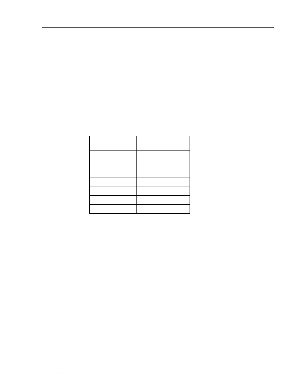
Table 4-1. Low Resistance Ranges with Maximum Current Ratings
Resistance range
Maximum Current
(ac or dc)
100.0 mΩ to 4.99 Ω 400 mA
5 to 29.9 Ω 250 mA
30 to 199.9 Ω 100 mA
200 to 499 Ω 40 mA
500 Ω to 1.999 kΩ 25 mA
2.00 to 5.00 kΩ 10 mA
5.00 to 10.0 kΩ 5 mA
Function Selection
To set the low resistance output:
1. Press L.
There are four selectable modes to the Low Resistance Source function: Resistance
2-wire and Resistance 4-wire, Short, and Open. The Mode selected the last time the
low resistance function was used is set.
The Short selection is used to short the Calibrator’s output terminals for zero point
compensation of the UUT. The Calibrator does not measure current in this mode. The
Open selection causes the Calibrator’s input impedance to go higher than 10 MΩ to
measure the maximum test voltage applied to the connectors. This measured voltage
is displayed in the PARAMETERS area of the display as Maximum value. Pressing
the Clear softkey will clear this value from the display during measurements.
2. If Open or Short is displayed, press the Mode softkey. Then, using the cursor keys
or rotary knob, highlight Resistance 2-Wire or Resistance 4-Wire and select it
by pressing Select or pushing in on the rotary knob.
3. If necessary, set the resistance value using the keyboard, cursor keys or rotary knob.
The resistance for this function is output through the terminals with either a 2-wire or 4-
wire connection. For 2-wire resistance calibration, connections to the UUT are made