5320A
Users Manual
7-16
280V
RMS
MAX
280V
RMS
MAX
CAT I
1000V
CAT II
600V
RMS MAX
20V PK
30A
RMS
MAX
20V PK
LO
LO - SENSE
, HI ,
mA
V
1500V PK
MAX
50V PK
MAX
20V PK
20V PK
N
L
PE
L1 L2 L3HES
OUTPUT
Z
L
, Z
GND
,
RCD
HI
LO
HI
LO
METER
METER
5320A
MULTIFUNCTION ELECTRICAL TESTER CALIBR
V
A
COM
INPUT
6500 APPLIANCE TESTER
Fluke 5320A
Fluke 6500
ehq056.eps
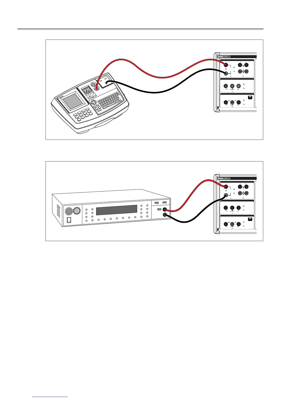
Figure 7-15. Active Leakage Current Calibration on Fluke 6500
280V
RMS
MAX
280V
RMS
MAX
CAT I
1000V
CAT II
600V
RMS MAX
20V PK
30A
RMS
MAX
20V PK
LO
LO - SENSE
, HI ,
mA
V
1500V PK
MAX
50V PK
MAX
20V PK
20V PK
N
L
PE
L1 L2 L3HES
OUTPUT
Z
L
, Z
GND
,
RCD
HI
LO
HI
LO
METER
METER
5320A
MULTIFUNCTION ELECTRICAL TESTER CALIBR
V
A
COM
INPUT
Associated Research
Linechek 510L
Fluke 5320A
ehq040.eps
Figure 7-16. Leakage Current Calibration on Earth Leakage Tester
Calibrating Residual Current Device (RCD) Testers
The Calibrator has two RCD modes for calibrating trip current and trip time of RCD
testers and multifunction installation testers with RCD testing capability.
WX Warning
To avoid electric shock, do not touch the L and N terminals
while calibrating testers in the RCD function. These terminals
have line voltage on them during this calibration process.
Calibrating RCD Trip Time
Trip time RCD calibrations are performed differently depending on the multiplier setting.
An example for each variation is listed below.
Calibrating Using 0.5 I Multiplier
The 0.5 I multiplier setting is used to calibrate non-trip RCDs. To perform a calibration
for Non-trip RCD function: