Calibrating Instruments
Calibrating RCD Test Functions 4
4-23
6. Press Start on the UUT.
When the level of test current flowing from the UUT reaches the set nominal trip current
value, the Calibrator starts to measure current amplitude. The measuring process lasts for
several power line cycles. The Calibrator simulates tripping of a breaker by disconnecting
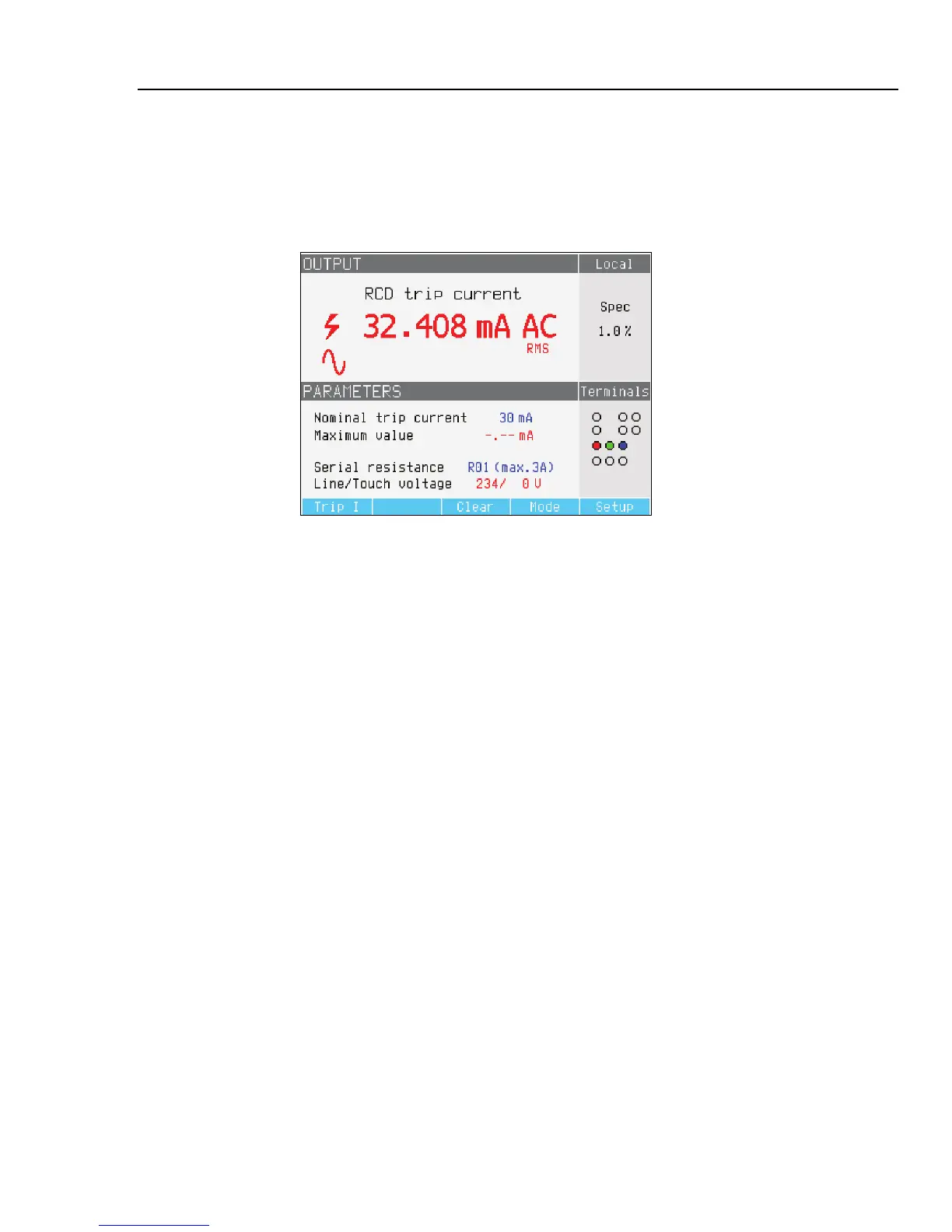
the output connectors and displays the measured trip current.
ehq65.bmp
Figure 4-15. RCD Trip Current Display
The Calibrator displays the following information for an RCD trip current calibration:
• UUT test signal polarity is indicated with one of the following graphic icons:
I Positive symmetrical ac current (SYMP)
J Negative symmetrical ac current (SYMN)
W Positive pulse of dc current (POS)
X Negative pulse of dc current (NEG
a dc current with positive polarity (DCP)
b dc current with negative polarity (DCN)
If the signal cannot be recognized, then “Not recognized” is displayed. If a negative
dc test current is detected, a “NEG” symbol is displayed. If a positive dc test current
is detected, a “POS” symbol is displayed. Phase is not displayed for dc sensitive
signals.
• Measured trip current as an rms value.
• Power/Touch voltage
Power Line Voltage
The Calibrator measures the power line voltage as a first step in the tripping procedure.
This voltage is measured after the output terminals are switched on.
Touch (contact) Voltage
Touch voltage is the voltage difference between N and PE potentials. UUTs can usually
measure this voltage and display it as a measured value or detect crossing over the safe
voltage level (25 to 50 volts typical) with an indication of this event. Touch voltage
generated by the Calibrator depends on selected series resistance and setup nominal trip
current. It is scanned and displayed in this field.