5320A
Users Manual
4-32
ehq66.bmp
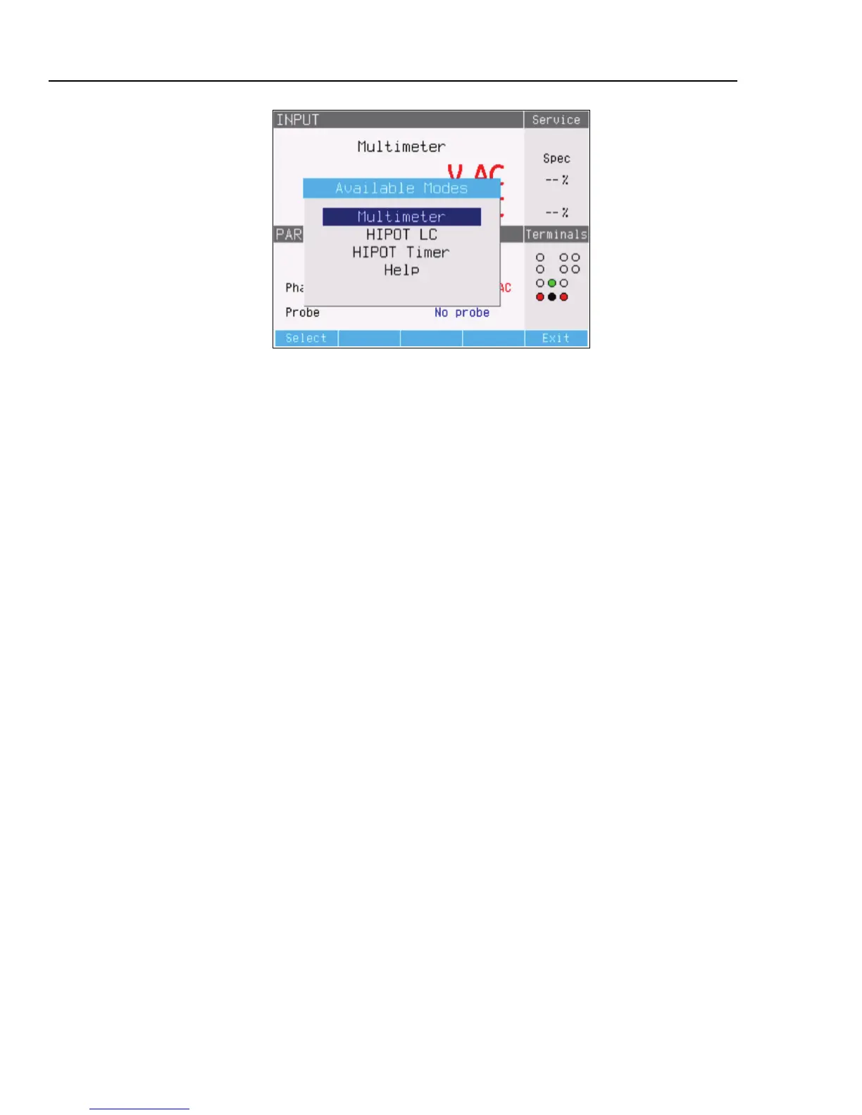
Figure 4-20. Multimeter Mode Selection
Measurements
To make a voltage measurement using the built-in multimeter:
1. Press M.
2. If necessary, press the AC/DC softkey to select between ac or dc mode.
WCaution
To prevent possible damage to the Calibrator, never connect
the COM or A connector to the Line (L) terminal of power mains.
3. Connect the test leads to the V and COM jacks.
Note
Whenever a voltage exceeding 50 volts is detected, the
F
icon appears in the display.
To make a current measurement using the built-in multimeter:
1. Press M.
2. If necessary, press the AC/DC softkey to select between ac or dc mode.
WCaution
To prevent possible damage to the Calibrator, never connect
the COM or A connector to the Line (L) terminal of power mains.
3. Connect the test leads to the A and COM jacks.
Note
Whenever a voltage exceeding 50 volts is detected, the
F
icon appears in the display.
The COM connector is the low signal connection for both voltage and current input. The
COM connector can be grounded or ungrounded (floating). When ungrounded, the
maximum voltage between COM and PE is 20 volts.
When both voltage and current are supplied to the meter’s inputs, both readings are
displayed in the output area of the display. In addition, a Phantom Power value is
calculated and displayed in the PARAMETERS area of the display.