5320A
Users Manual
7-12
280V
RMS
MAX
280V
RMS
MAX
CAT I
1000V
CAT II
600V
RMS MAX
20V PK
30A
RMS
MAX
20V PK
LO
LO - SENSE
, HI ,
mA
V
1500V PK
MAX
50V PK
MAX
20V PK
20V PK
N
L
PE
L1 L2 L3HES
OUTPUT
Z
L
, Z
GND
,
RCD
HI
LO
HI
LO
METER
METER
5320A
MULTIFUNCTION ELECTRICAL TESTER CALIBR
V
A
COM
INPUT
6500 APPLIANCE TESTER
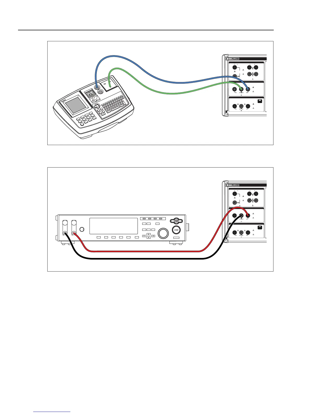
Fluke 5320A
Fluke 6500
ehq035.eps
Figure 7-10. Ground Bond Resistance Calibration on Fluke 6500 Using Single Test Leads
280V
RMS
MAX
280V
RMS
MAX
CAT I
1000V
CAT II
600V
RMS MAX
20V PK
30A
RMS
MAX
20V PK
LO
LO - SENSE
, HI ,
mA
V
1500V PK
MAX
50V PK
MAX
20V PK
20V PK
N
L
PE
L1 L2 L3HES
OUTPUT
Z
L
, Z
GND
,
RCD
HI
LO
HI
LO
METER
METER
5320A
MULTIFUNCTION ELECTRICAL TESTER CALIBR
V
A
COM
INPUT
Fluke 5320A
ehq055.eps
Figure 7-11. Ground Bond Resistance Calibration on Bench Ground Bond Tester
Calibrating Line Impedance Testers
The Calibrator’s Line Impedance calibration function calibrates the line impedance
function of loop testers and multifunction installation testers with loop testing capability.
Different models of installation testers use different test current levels to avoid tripping
protective circuits. The Calibrator limits the amount of test current that can be used
during a line impedance calibration.
WX Warning
To avoid electric shock, do not touch the L, PE, or N terminals
on the Calibrator or UUT while performing a Line Impedance
calibration. Line voltage is present on these leads during this
calibration.
To perform a Line Impedance calibration: