Applications
Calibrating Ground Bond Resistance Testers 7
7-11
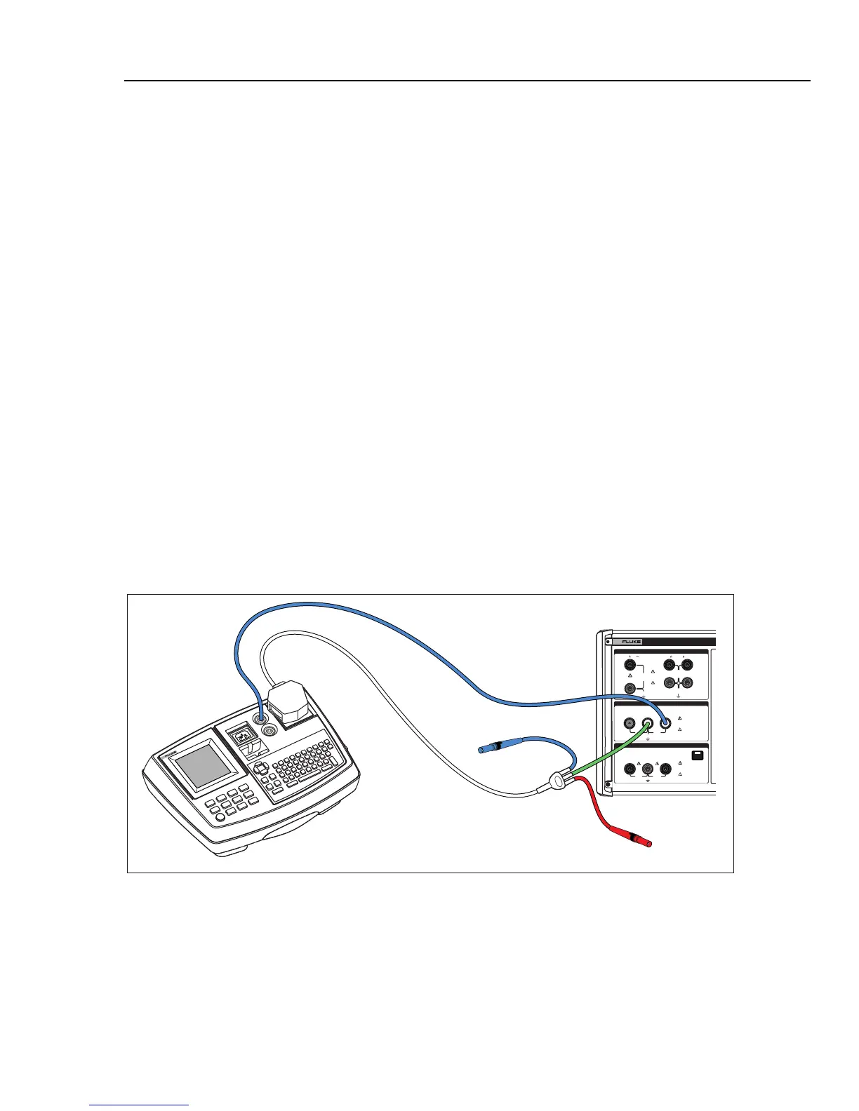
1. Using Figures 7-9 through 7-11, connect the UUT to the Z
GND
PE and N terminals of
the Calibrator.
2. Press G.
3. If OPEN is displayed in the output area of the display, press the MODE softkey.
Then, using the cursor keys or rotary knob, highlight Resistance and select it by
pressing the Select softkey or pushing in on the rotary knob.
4. If necessary, adjust the resistance value to the desired resistance.
5. If necessary, select the Ground Bond Resistance function on the UUT.
W Caution
Ensure the UUT test current does not exceed the maximum
allowed test current displayed in the parameters area of the
Calibrator’s display. The resistors can handle higher current
levels for short time durations (above the level displayed on the
Calibrator). See the specifications section for the maximum
short-term allowable current per resistor.
6. Press O.
7. Press Start on the UUT.
The test current flowing through the UUT and Calibrator is displayed in the
PARAMETERS area of the Calibrator’s display.
8. Compare the UUT resistance reading with the resistance in the Calibrator’s display.
9. Press S to disconnect the output terminals from the UUT.
280V
RMS
MAX
280V
RMS
MAX
CAT I
1000V
CAT II
600V
RMS MAX
20V PK
30A
RMS
MAX
20V PK
LO
LO - SENSE
, HI ,
mA
V
1500V PK
MAX
50V PK
MAX
20V PK
20V PK
N
L
PE
L1 L2 L3HES
OUTPUT
Z
L
, Z
GND
,
RCD
HI
LO
HI
LO
METER
METER
5320A
MULTIFUNCTION ELECTRICAL TESTER CALIBR
V
A
COM
INPUT
6500 APPLIANCE TESTER
Fluke 5320A
Fluke 6500
ehq034.eps
Figure 7-9. Ground Bond Resistance Calibration on Fluke 6500 Using the Cable Adapter