5320A
Users Manual
6-6
Verifying Calibrator Operation
The following sections describe the procedure used to verify the Calibrator is operating
correctly and within specifications. Ensure the Calibrator has been in a temperature stable
environment for at least 8 hours before starting the verification process.
Preparing for Calibrator Verification
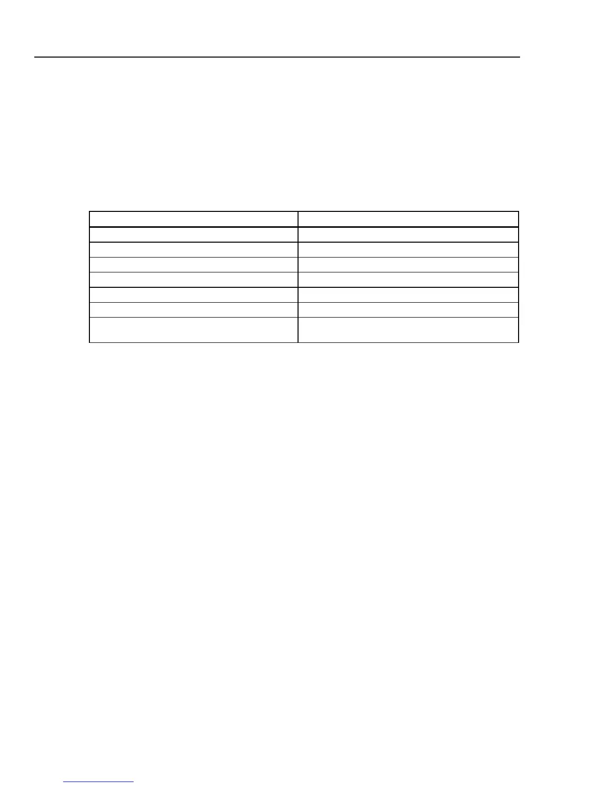
Table 6-3 lists the equipment required to perform Calibrator verification.
Table 6-3. Required Verification Test Equipment
Test Equipment Recommended Model
Multimeter with 4-wire ohms capability Fluke 8508A or equivalent
Megaohmmeter with 3 test leads Quadtech 1865 or equivalent
Multifunction calibrator Fluke 5500A, Fluke 5520A or equivalent
Frequency counter Fluke PM 6690 or equivalent
Distortion analyzer HP/Agilent 8903B or equivalent
10 kV ac/dc source As available
40 kV ac/dc source
(applies only to 5320A with 40 kV option)
As available
Power up the Calibrator and test equipment and ensure power has been applied for at
least one hour before starting the verification process.
Performing Calibrator Verification
The Calibrator verification procedure consists of the following basic steps:
• Low resistance source
• High resistance source
• Ground bond (and loop/line impedance) resistance source
• Leakage current ac ranges 300 uA, 3 mA, 30 mA
• RCD trip current
• RCD trip time
• Calibrator ac/dc voltage on ranges 30 V ac, 100 V ac, 300 V ac, 600 V ac, 100 V dc,
600 V dc (5320A/VLC models only)
• Multimeter voltage ranges 10 V, 100 V, 1000 V
• Multimeter current ranges 300 mA, 3 A, 30 A
• Frequency nominal value 400 Hz
• Hipot leakage current
• 10 kV ac/dc voltage divider verification
• 40 kV ac/dc voltage divider verification (5320A with 40 kV option)
After connecting the Calibrator to the power mains, turn power on and let the Calibrator
warmup for at least one hour in a laboratory with a temperature of 23 ±1 ºC before
proceeding with the verification.
The following steps use measuring points that are specified in Tables 6-4 to 6-16.
Low Resistance Source Verification
1. Connect the low resistance source output to a standard multimeter. Use a 4-wire
connection and setup the Multimeter for a 4-wire ohms measurement.