5320A
Users Manual
7-24
280V
RMS
MAX
280V
RMS
MAX
CAT I
1000V
CAT II
600V
RMS MAX
20V PK
30A
RMS
MAX
20V PK
LO
LO - SENSE
, HI ,
mA
V
1500V PK
MAX
50V PK
MAX
20V PK
20V PK
N
L
PE
L1 L2 L3HES
OUTPUT
Z
L
, Z
GND
,
RCD
HI
LO
HI
LO
METER
METER
5320A
MULTIFUNCTION ELECTRICAL TESTER CALIBR
V
A
COM
INPUT
6500 APPLIANCE TESTER
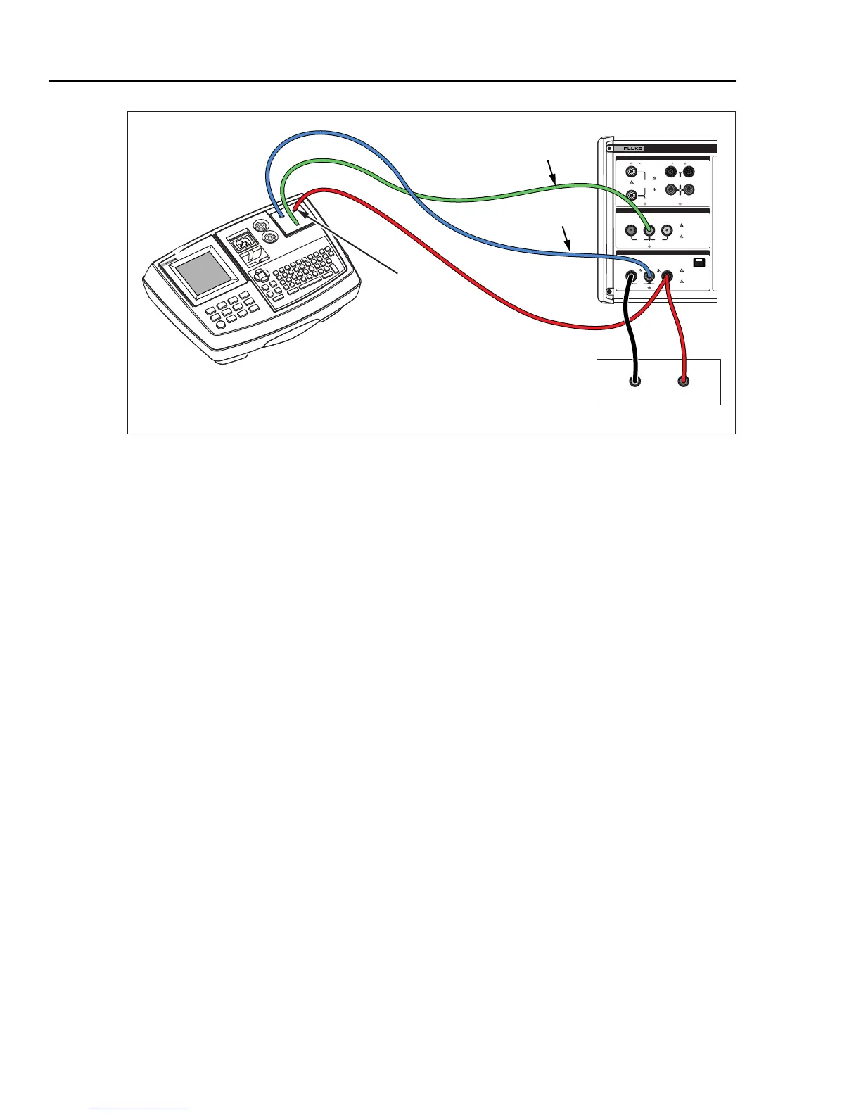
Fluke 5320A
Fluke 6500
External Load
Line Terminal
Protection Earth
Terminal
Neutral Terminal
ehq057.eps
Figure 7-22. Voltage and Current Meter Calibration Using single wires
Calibrating High Voltage Sources (Hipots) with a High
Voltage Probe
The Calibrator can measure voltages above 1,500 volts by using a high voltage adapter or
high voltage probe.
Measuring High Voltage with the High Voltage Adapter
The 10 kV High Voltage adapter is a voltage divider that steps the voltage down by a
1:1000 ratio. When purchased with the Calibrator, the High Voltage probe and Calibrator
are calibrated together to give better accuracy. To measure a voltage with the High
Voltage Probe:
1. Using Figure 7-23, connect the UUT through the High Voltage adapter and the
Calibrator.
2. Press M.
3. If 10 kV is not already displayed after Probe in the PARAMETERS area of the
Calibrator’s display, press the Probe softkey repeatedly until 10 kV is selected.