Front-Panel Operation
Controls and Indicators 3
3-7
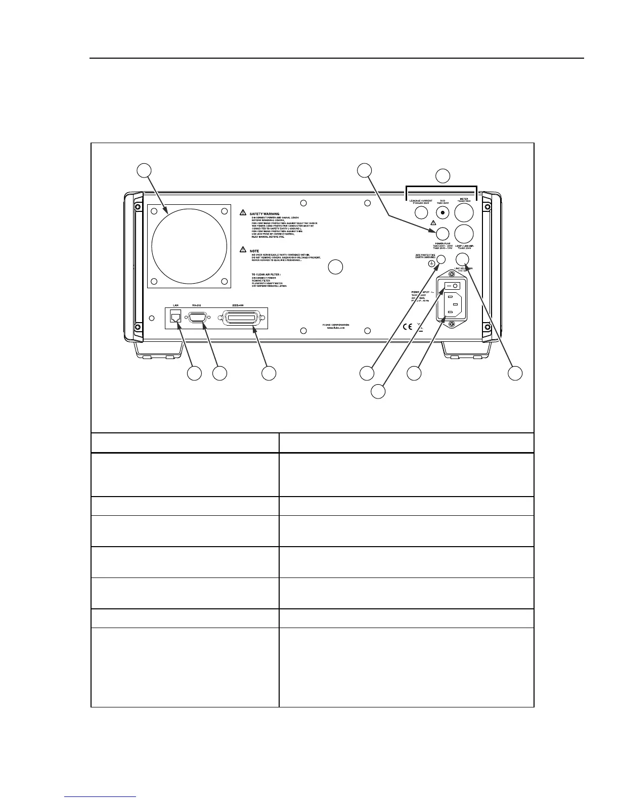
Rear Panel
Table 3-2 lists the items found on the Calibrator’s rear panel.
Table 3-2. Rear-Panel Features
1
7 58910 4
6
2
3
elv002.eps
Item Description
A Fan Filter The filter covers the air intake to keep dust and debris out of
the chassis. A fan inside the Calibrator provides a constant
cooling air flow throughout the chassis.
B Line Power Fuse Holder The line power fuse. Refer to “Accessing the Fuses”.
C Signal Fuse Holders These fuses protect the signal outputs and inputs. Refer to
“Accessing the Fuses”.
D Line Voltage Selection Switch Selects the line voltage. Refer to Selecting Line Voltage
earlier in the manual.
E AC Power Input Connector A grounded male three-prong connector that accepts the line
power cord.
F AC Power Switch Turns Calibrator ac power on and off.
G Chassis Ground Binding Post A binding post that is internally grounded to the chassis. If the
Calibrator is the ground reference point in a system, this
binding post can be used for connecting other instruments to
earth ground. (The chassis is normally connected to earth
ground through the three conductor line cord instead of
through the earth ground binding post.)