5320A
Users Manual
3-8
Table 3-2. Rear-Panel Features (cont.)
Item Description
H IEEE 488 Port A standard interface for operating the Calibrator in remote
control as a Talker or Listener on the IEEE 488 Bus. Refer
to Chapter 5 of this Manual for bus connection and remote
programming instructions.
I RS-232 Port A female serial port (DCE) connector for transmitting
internal calibration constant data to a printer, monitor, or
host computer, and for remote control of the Calibrator.
Chapter 5 of this Manual describes proper cabling, how to
set up the serial interface, and how to transmit data from
the Calibrator.
J LAN Port An RJ45 LAN connector for remote control of the
Calibrator. Chapter 5 of this Manual describes proper
cabling, how to set up the LAN interface, and how to
transmit data from the Calibrator.
Display Panel Features
The 16 color active LCD display panel is used to display the Calibrator’s status, errors,
measured values, and set parameters. Each Calibrator function has its own screen layout
to accommodate the appropriate data. A system of Menu selections for Calibrator setups,
function controls, and help text is also displayed.
Table 3-3 lists the different areas of the display and the information contained in them.
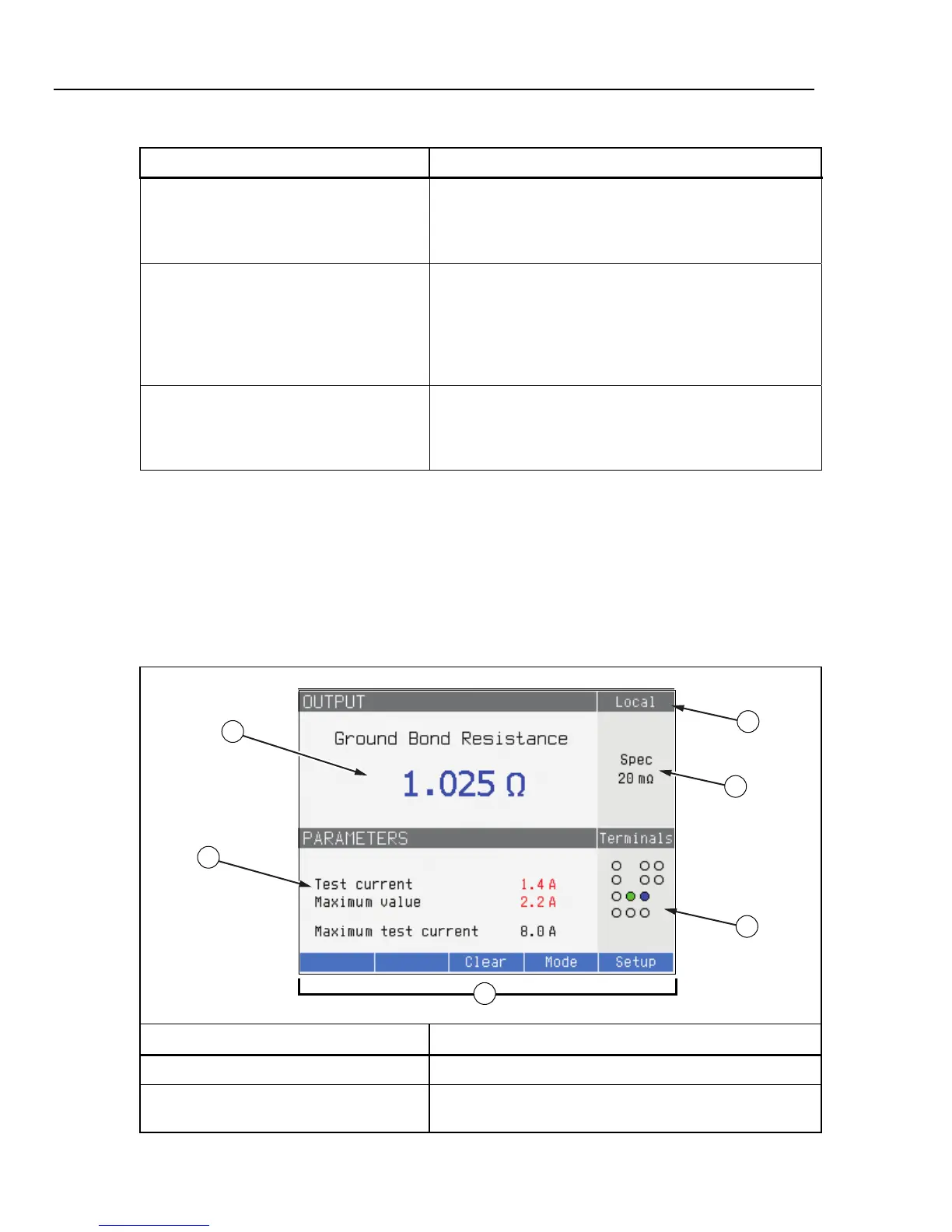
Table 3-3. Display Panel Features
1
2
4
5
6
3
ehq003.eps
Item Description
A Output Displays the selected function and their parameters.
[1]
B Parameters Displays auxiliary measurements and parameters for the
selected function.
[1]