Calibrating Instruments
Performing Leakage Current Calibration 4
4-17
Calibrating Passive Leakage Current
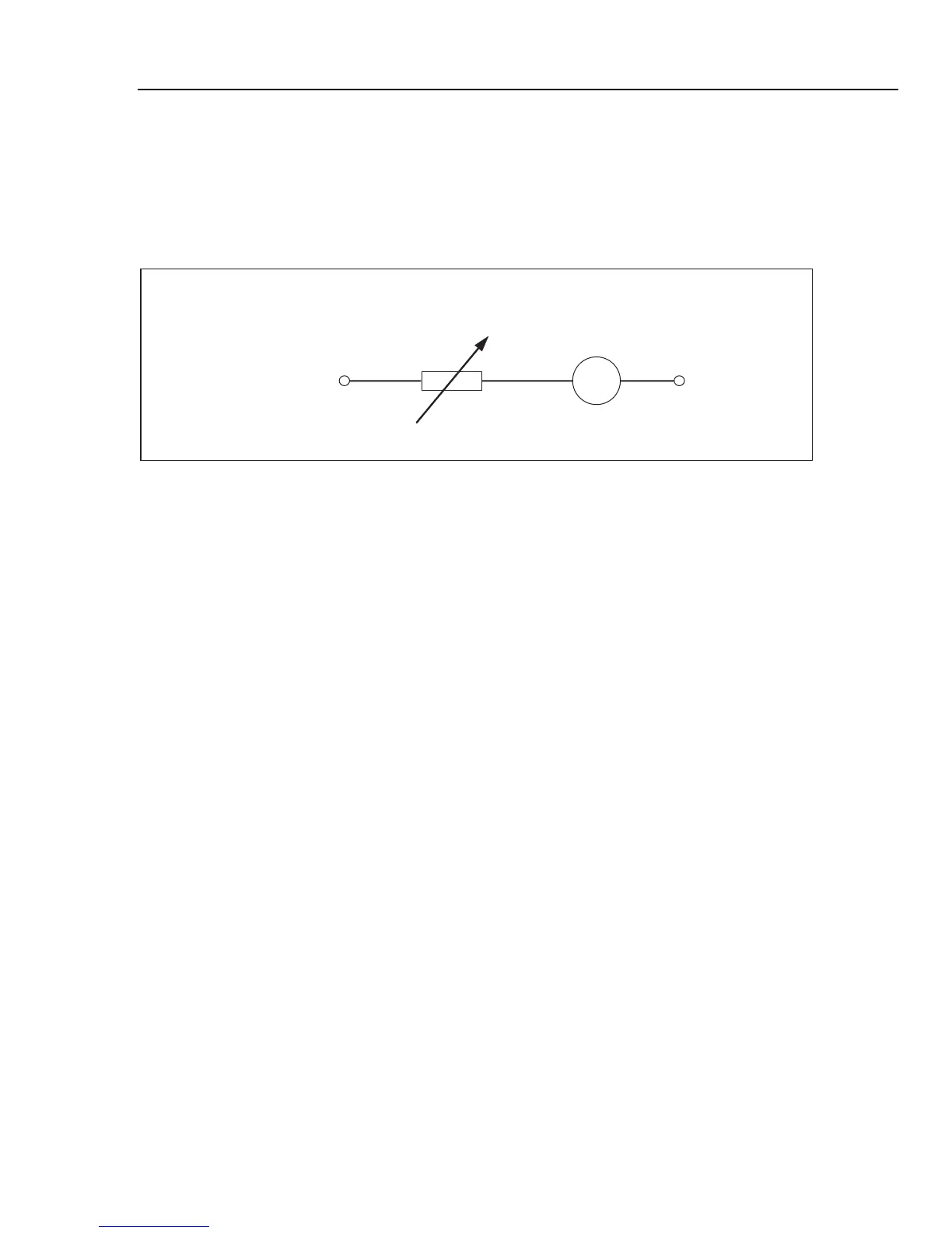
For passive leakage current calibration, the Calibrator presents a passive variable
resistance on the OUTPUT HI and LO connectors. When connected to the Calibrator, the
UUT applies a voltage to this resistance and the Calibrator displays the current flowing
through the resistance. Figure 4-10 shows the simplified calibrator circuit for this
function.
R
OUTPUT V, HIΩ, mA~
HI LO
mA
ehq015.eps
Figure 4-10. Simplified Passive Leakage Current Schematic
The Calibrator’s internal ammeter measures the current flowing from the UUT’s source
terminal (L) to its protected earth (PE) terminal. The Calibrator’s leakage current range is
0.1 to 30 mA, with an external applied voltage from 25 V to 250 V ac or dc.
Before Passive Leakage Current calibration can be performed, a nominal leakage current
must be entered. To enter a nominal leakage current (Id nom):
1. Press the Id nom softkey.
2. Using the keypad, type in the nominal leakage current.
Note
The softkeys can be used to select the units multiplier of A, mA or
μ
A
instead of the exponent key (D).
3. Press E.
Note
The measured current may be different than the entered nominal current by
up to
±
10 %, depending on power supply voltage and set nominal value.
Note
If the UUT is not connected to the Hi and LO terminals of the Calibrator,
an “Output/Input overload” message is displayed. This same message is
displayed if the LC fuse is open.
To start a Passive Leakage Current calibration:
1. Press N.
2. If Passive Leakage Current is not already displayed, press the Mode softkey.
3. Using the cursor keys or rotary knob, highlight the Passive selection and either
press the Select softkey or press in on the rotary knob.
4. Referring to the terminals part of the display, connect the UUT to the Calibrator.
5. Press the START button on the UUT.