5320A
Users Manual
4-10
ehq024.bmp
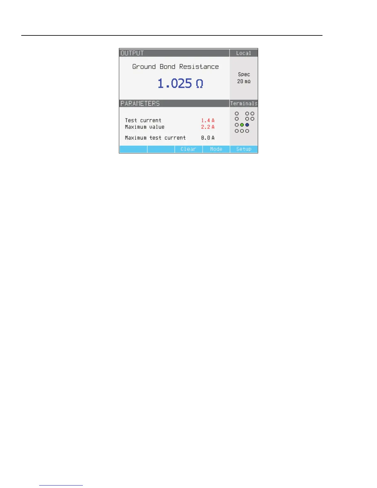
Figure 4-6. Ground Bond Resistance Display
While connected to the UUT, the Calibrator monitors the voltage and current appearing
across the resistance. If the current or voltage exceeds acceptable limits, the Calibrator
will disconnect the output terminals and display an error message. The actual current
flowing through the resistance, along with the maximum allowed current, is displayed in
the PARAMETERS area of the display.
With the output connected, you can adjust the resistance value with the rotary knob or
numeric keypad. Any new values set through the front panel take approximately 500 ms
to appear on the output terminals. If during the adjustment, the current or voltage exceeds
acceptable limits, the output terminals will be disconnected and an error message is
displayed. If the set value should exceed the upper range limit or lower range limit, the
Calibrator displays “Value too high” or “Value too low” respectively.
There are no special parameters for the Ground Bond Resistance function.
Setting the Loop and Line Impedance Output
For calibrating loop and line impedance functions of loop testers and multifunction
installation testers, the Calibrator presents a resistance from 25 mΩ to 1.8 kΩ on its
output terminals. Table 4-3 lists the 16 selectable resistance settings along with their
maximum current and voltage ratings.
Setting the output for loop impedance calibration is almost identical to that for line
impedance. The only difference is the connection between the UUT and the Calibrator.
For line impedance calibration, the resistance is inserted between the N terminal on the
front panel and the Neutral of the power line input on the rear panel. A calibrated
resistance is created using the selected resistance in series with the real residual line
impedance in the power line socket and the resistance of the power line cable.