Calibrating Instruments
Setting the Loop and Line Impedance Output 4
4-11
Neutral
Line
R
Front Panel
Z
L
, Z
GND
, RCD
N
Compensator
L
Fixed Mains
Socket/Outlet
ehq013.eps
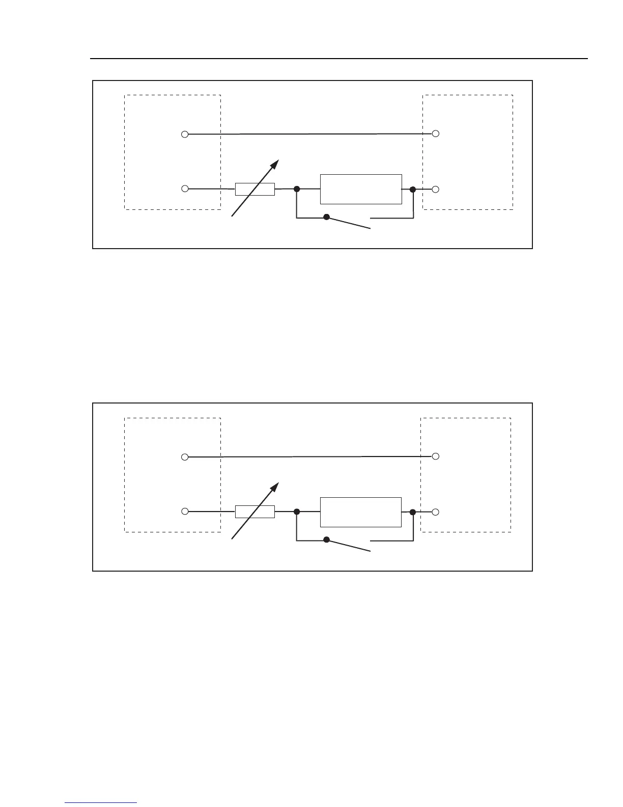
Figure 4-7. Simplified Line Impedance source Schematic
For loop impedance calibration, the resistance is inserted between the PE terminal on the
front panel and PE (protective earth ground) of the power line input on the rear panel.
During a loop impedance calibration, test current flows from the L wire in the mains to
the PE terminal. Loop impedance calibration will not trip a protected circuit unless the
test current of the UUT is higher than the nominal trip current of the installed residual
current device (current breaker).
Calibrated resistance is created by the resistors in the source, together with the real
residual loop impedance in the power line socket and power line cable.
Neutral
Line
R
Front Panel
Z
L
, Z
GND
, RCD
PE
Compensator
L
Fixed Mains
Socket/Outlet
ehq014.eps
Figure 4-8. Simplified Loop Impedance Source Schematic
To set the Loop or Line Impedance Output:
1. Press Z.
2. If the displayed function is not the desired function, press the Mode softkey.
3. Using the cursor keys or rotary knob, highlight either Loop or Line and either press
Select or press in on the rotary knob.
The value used the last time the Loop or Line impedance function was used is set and
displayed in the output area of the display.