5320A
Users Manual
4-6
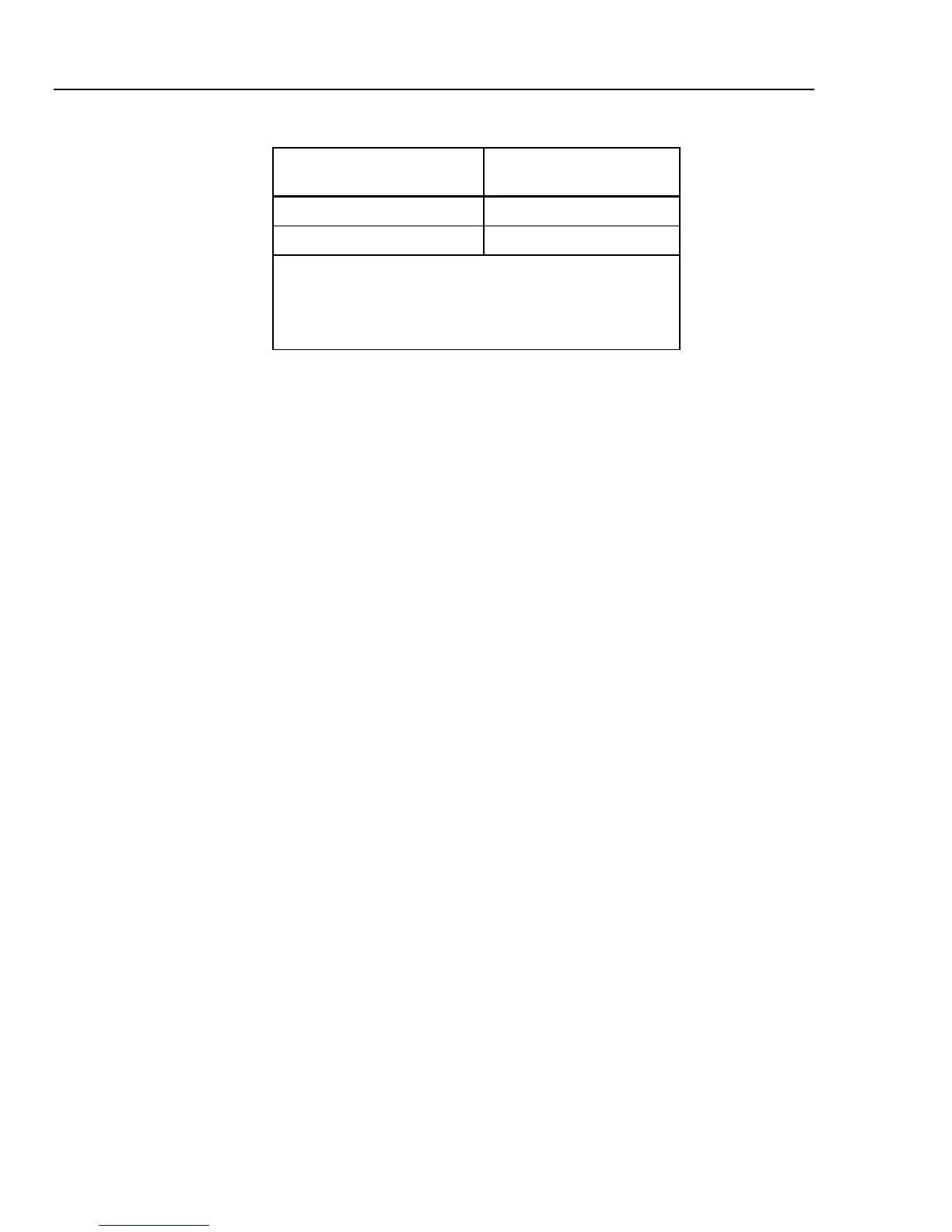
Table 4-2. High Resistance Ranges with Maximum Voltage Rating (cont.)
Resistance range
Maximum applicable
voltage (AC+DC)PEAK
1.0000 to 10.000 GΩ 1,575 V
[1]
100 GΩ 1,575 V
[1]
Notes:
[1] Maximum test voltage with the supplied banana leads is
1000 Vrms. For higher voltages, use leads rated at 1575 V
or above.
An optional high voltage divider/resistance multiplier is available to increase the
resistance range to 10 TΩ with a maximum test voltage of 5.5 kV.
Function Selection
To set the high resistance output:
1. Press H.
There are three selectable modes to the High Resistance Source function: Resistance,
100 GΩ, and Short. The mode selected the last time the High Resistance function
was used is set.
The Short selection is used to short the Calibrator’s output terminals to test for
maximum test current. This measured current is displayed in the PARAMETERS
area of the display as Maximum value.
2. If Short is displayed, press the Mode softkey. Then, using the cursor keys or rotary
knob, highlight Resistance and select it by pressing Select or pushing in on the
rotary knob.
3. The value established the last time the high resistance function was used is set and
displayed in the output area of the display.
4. If necessary, use the keypad, cursor keys, or rotary knob to set the resistance value.
For this function, the resistance is output through the terminals with either a 2-wire or 3-
wire connection. For 2-wire resistance calibration, connections to the UUT are made
through the HIΩ HI and HIΩ LO terminals. For 3-wire calibration, ground potential is
available on the METER COM terminal. Whether or not the output is grounded is
indicated in the terminals part of the display.
Note
3-wire resistance mode is sometimes necessary to improve calibration
stability. This is especially true for resistances over 100 M
Ω
. The third
terminal is usually connected to the guard or ground terminal on the UUT.
If the UUT is equipped with a GND terminal, it should be connected to the
PE terminal.
The resistance on the Calibrator’s terminals can either be floating or grounded. When
grounded, the HIΩ LO terminal is connected to earth ground in the power line socket
through an internal relay. See “To switch between grounded and ungrounded output”
below to change this setting.