Calibrating Instruments
Setting the Ground Bond Resistance Output 4
4-9
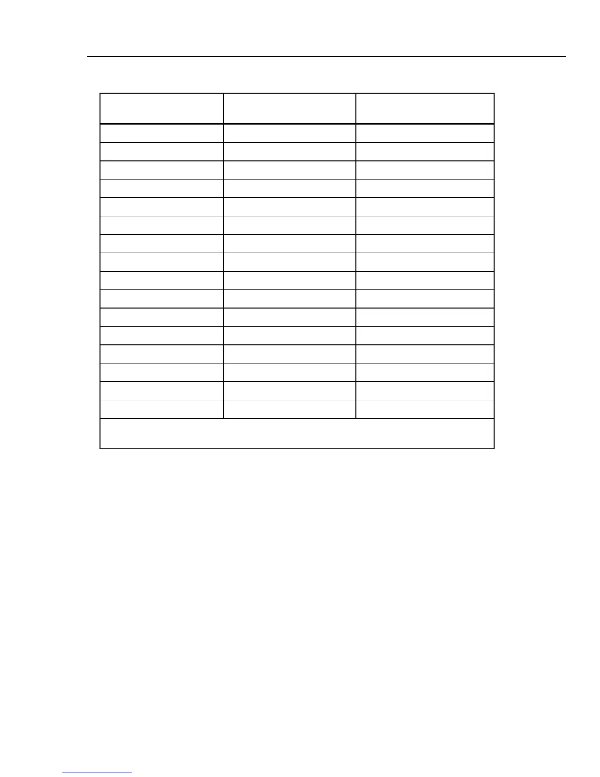
Table 4-3. Selectable Resistance with Maximum Continuous Current and Voltage
Nominal Resistance Value Maximum Continuous Test
Current AC(RMS) or DC
[1]
Maximum Continuous Test
Voltage AC(RMS) or DC
25 mΩ 30 A 0.75 V
50 mΩ 28 A 1.4 V
100 mΩ 25 A 2.6 V
330 mΩ 14 A 3.6 V
500 mΩ 10 A 5 V
1 Ω 8 A 8 V
1.8 Ω 6 A 12 V
5 Ω 3.2 A 16 V
10 Ω 2.0 A 20 V
18 Ω 1.5 A 30 V
50 Ω 0.8 A 40 V
100 Ω 0.5 A 50 V
180 Ω 0.25 A 50 V
500 Ω 0.1 A 50 V
1 kΩ 0.05 A 50 V
1.8 kΩ 0.03 A 50 V
Note:
[1] For short-term allowable test current, see the specifications in chapter 1 of this manual.
To set the Ground Bond resistance output:
1. Press G.
The value used the last time the ground bond resistance function was used is set and
displayed in the output area of the display.
2. If necessary, set the resistance value using the rotary knob. The keypad can also be
used to enter a value. If the entered value is not exactly one of the 16 possible
selections, the resistance closest to the value entered will be selected.
3. Using the Terminals part of the display as a guide, connect the UUT’s terminals to
the Calibrator’s PE and N terminals of the Z
L
, Z
GND
and RCD terminals. These
terminals are always floating from ground.
4. After confirming all settings and connections are correct, press O to connect the
UUT to the selected resistance.