Applications
Calibrating Line Impedance Testers 7
7-13
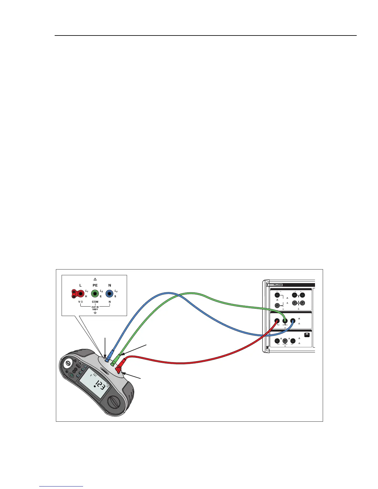
1. Using Figure 7-12, connect the UUT to the L, PE and N terminals of the Calibrator.
For some line impedance testers, PE does not need to be connected.
2. Press the Setup softkey and set the desired residual impedance correction. See
“Selecting the Residual Impedance Correction Mode” in Chapter 4 of this manual for
more information on this correction. When set, press the EXIT softkey repeatedly
until returned to the main Line Impedance display.
3. Press Z.
4. If Line Impedance does not already appear in the output area of the display, press
the Mode softkey. Then, using the cursor keys or rotary knob, highlight Line and
select it by pressing the Select softkey or pushing in on the rotary knob.
5. On the UUT, select the Line Impedance function, test signal, and test condition.
Refer to the UUT manual for information on setting these variables.
6. Press O.
7. Press Start or Test on the UUT.
During the calibration, the PARAMETERS area of the Calibrator’s display indicates
the measured test signal polarity, amplitude, and prospective fault current (PFC).
8. When the UUT displays the measured line impedance, compare it to the impedance
displayed in the output area of the Calibrator’s display.
Note
When a new impedance is set on the Calibrator, the resistance change takes
approximately 500 milliseconds.
10. Press S to disconnect the output terminals from the UUT.
280V
RMS
MAX
280V
RMS
MAX
CAT I
1000V
CAT II
600V
RMS MAX
20V PK
30A
RMS
MAX
20V PK
LO
LO - SENSE
, HI ,
mA
V
1500V PK
MAX
50V PK
MAX
20V PK
20V PK
N
L
PE
L1 L2 L3HES
OUTPUT
Z
L
, Z
GND
,
RCD
HI
LO
HI
LO
METER
METER
5320A
MULTIFUNCTION ELECTRICAL TESTER CALIBR
V
A
COM
INPUT
Fluke 1653
Fluke 5320A
PE
(L2/Green)
L
(L1/Red)
N
(L3/Blue)
ehq037.eps
Figure 7-12. Line and Loop Impedance Calibration on a Fluke 1653